Liquid-cooling heat sink and heat exchanger thereof
- Summary
- Abstract
- Description
- Claims
- Application Information
AI Technical Summary
Benefits of technology
Problems solved by technology
Method used
Image

Examples
first embodiment
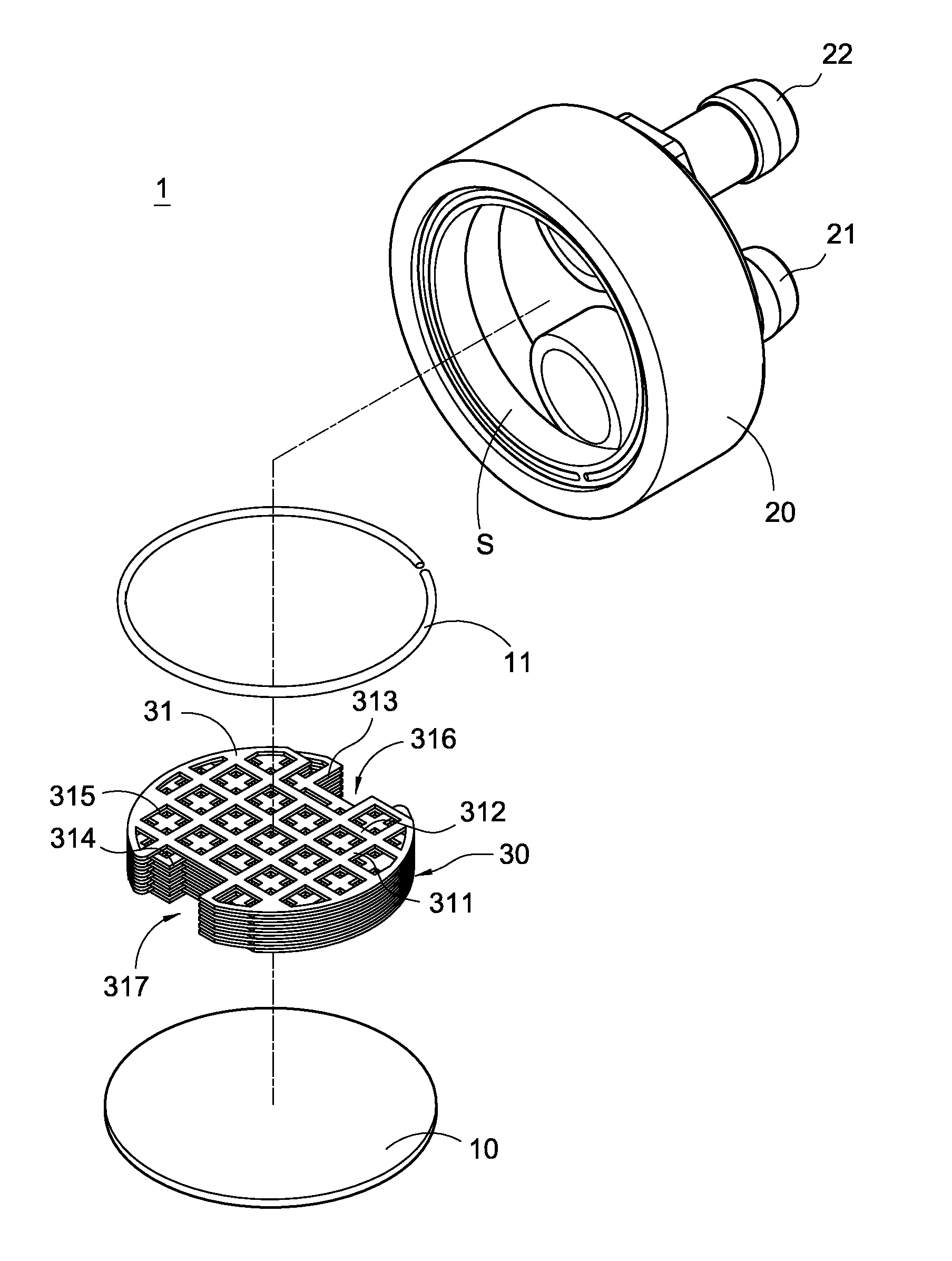
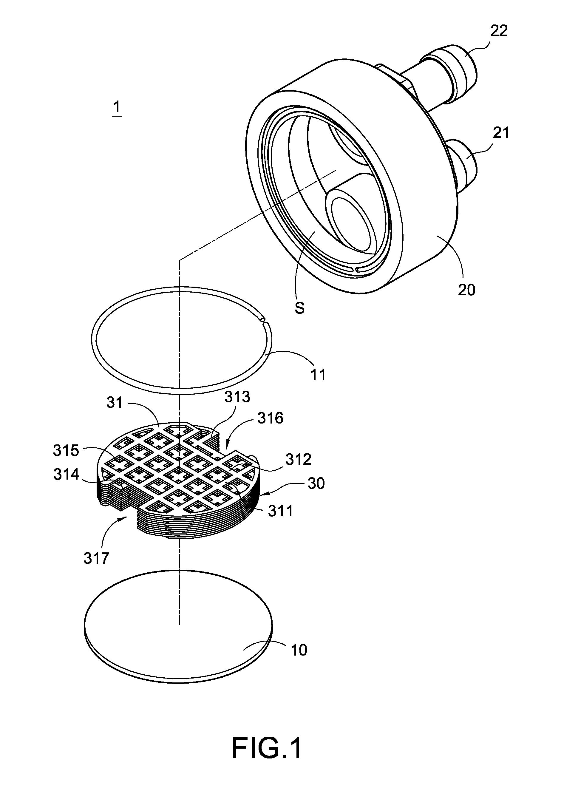
[0041]Please refer to FIG. 1, which is an exploded perspective view showing the present invention. The present invention provides a liquid-cooling heat sink 1, which includes a base 10, a cover 20, and a heat exchanger 30.
[0042]The base 10 is made of metallic materials having high heat conductivity such as aluminum, copper or the like. The base 10 can be formed into any suitable shape. In the first embodiment, the base 10 is formed into a flat disk. After the cover 20 covers the base 10, an accommodating space S is formed between the base 10 and the cover 20 for allowing a cooling liquid and the heat exchanger 30 to be disposed therein. As shown in FIG. 3, the bottom surface of the base 10 is brought into thermal contact with a heat source (not shown) to be cooled, thereby conducting the heat generated by the heat source to the heat exchanger 30.
[0043]The cover 20 is also made of metallic materials having high heat conductivity such as aluminum, copper or the like. The cover 20 is f...
third embodiment
[0059]In the third embodiment, each heat-dissipating plate 31b has a plurality of first dividing strips 311b and a plurality of second dividing strips 312b intersecting with the first dividing strips 311b. It should be noted that, in FIG. 12, the first dividing strips 311b and the second dividing strips 312b intersect with each other perpendicularly to form a cross structure, which is merely a preferred embodiment. Of course, it can be contemplated that, the first dividing strips 311b and the second dividing strips 312b may intersect with each other to form an X-shaped structure, which also achieves the same effect. One side of each heat-dissipating plate 31b is formed with a plurality of notches 313b in the direction of the first dividing strips 311b. Another side of each heat-dissipating plate 31b is formed with a plurality of notches 314b in the direction of the second dividing strips 312b. The adjacent two first dividing strips 311b and adjacent two second dividing strips 312b d...
second embodiment
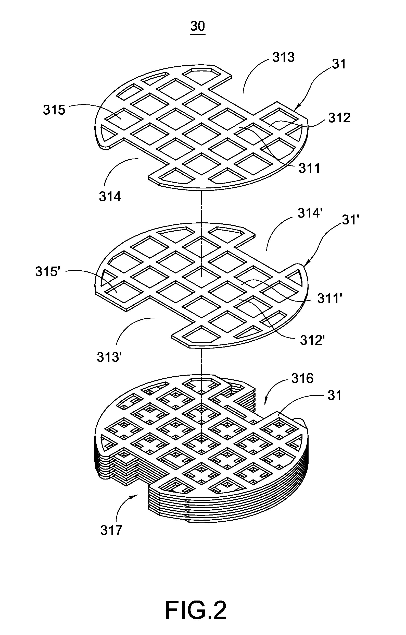
[0064]Although the present invention has been described with reference to the above preferred embodiments, the profile of the heat-dissipating plate 31, 31′ and the shapes of the dividing strips 311, 311′ and the through-holes 315, 315′ can be changed in a manner equivalent to those of the above preferred embodiments. For example, in the second embodiment, the dividing strips 311a, 311a′ and the through-holes 315, 315a are formed into a curved shape with respect to the line connecting the first notch 313 and the second notch 314. However, the dividing strips 311a, 311a′ and the through-holes 315a, 315a′ may be arranged to be parallel to or inclined with respect to the line connecting the first notch 313 and the second notch 314 as long as the dividing strips 311a, 311a′ intersect with each other to divide the through-holes 315a, 315a′ of the lower heat-dissipating plate 31a, 31a′ into a plurality of multi-direction sub-channels.
[0065]In the first embodiment and the second embodiment...
PUM
 Abstract
Description
Claims
Application Information
 - Generate Ideas
- Intellectual Property
- Life Sciences
- Materials
- Tech Scout
- Unparalleled Data Quality
- Higher Quality Content
- 60% Fewer Hallucinations
Browse by: Latest US Patents, China's latest patents, Technical Efficacy Thesaurus, Application Domain, Technology Topic, Popular Technical Reports.
© 2025 PatSnap. All rights reserved.Legal|Privacy policy|Modern Slavery Act Transparency Statement|Sitemap|About US| Contact US: help@patsnap.com