Method and Apparatus for Charging Batteries

a battery charger and charging method technology, applied in the field of battery chargers, can solve the problems of increasing the size and cost of battery chargers, affecting the efficiency of home appliances, and generating heat from power loss of switching devices in dc/dc converters, etc., and achieves the effects of small capacitance, large charge current, and rapid charging

Active Publication Date: 2012-04-05
LENOVO PC INT
View PDF11 Cites 24 Cited by
  • Summary
  • Abstract
  • Description
  • Claims
  • Application Information

AI Technical Summary

Benefits of technology

[0011]As a result of the analysis of the battery charging properties, it has been found that battery chargers are not required to put the ripple content within a predetermined range over the entire charge duration from the beginning and the end of the charge, which is different from a DC / DC converter supplying power to a device. Accordingly, when a switching frequency can be lowered within a certain range of the charge duration on the basis of such charge properties, rapid charging can be performed without using a battery charger having a switching device with a capacity larger than what's required. The present disclosure provides a battery charger capable of charging a battery with a relatively large charge current using a switching device with a relatively small capacitance. In accordance with a preferred embodiment of the present invention, a battery charger includes a switching device and a controller. The switching device performs switching of a DC input voltage at a predetermined switching frequency to generate an output voltage, and the output voltage being utilized for charging the battery. The controller allows the switching device to operate at a first switching frequency immediately after starting of charging and to operate at a second switching frequency when a frequency changing condition holds. The second switching frequency is higher than that of the first switching frequency.

Problems solved by technology

However, it is not preferable to have the output voltage being lowered more than what's required because the battery will not be able to reach a full charge capacity at the completion of the battery charging process.
Since the battery chargers for quickly charging such quick-charge type lithium batteries have to supply a large current, heat generated due to power loss of a switching device in a DC / DC converter begins to present a problem.
In order to cope with this problem, a large-capacity switching device may be used, which introduces another problem of an increase in size and cost of battery chargers.

Method used


Image

  • Method and Apparatus for Charging Batteries
  • Method and Apparatus for Charging Batteries
  • Method and Apparatus for Charging Batteries

Examples


Embodiment Construction

[Configuration of a Portable Computer]

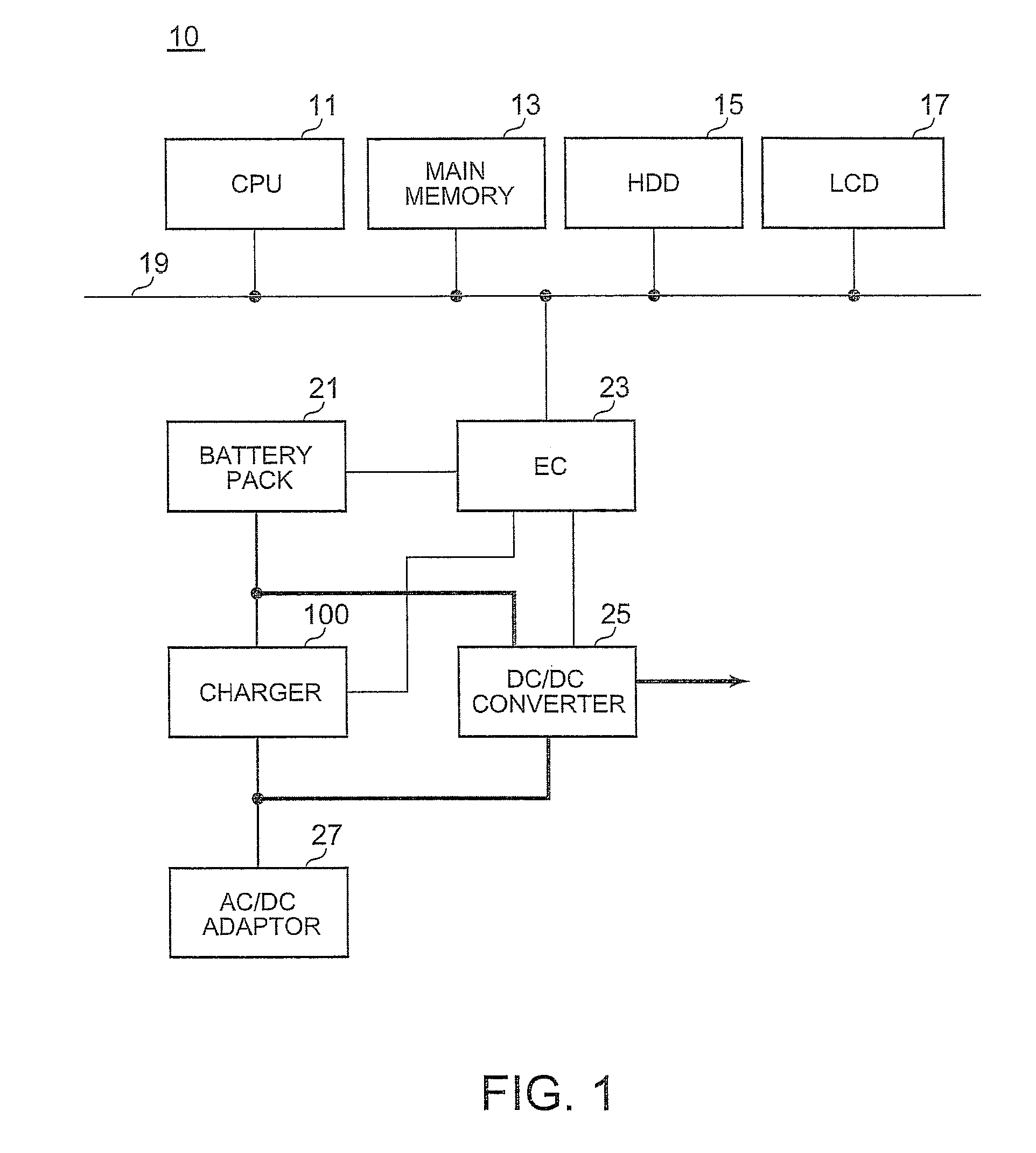
[0021]FIG. 1 is a block diagram of a portable computer 10 according to the present embodiment. In FIG. 1, thick lines connecting elements represent power lines and thin lines represent signal lines. The portable computer 10 includes a CPU 11, a main memory 13, a hard disk drive (HDD) 15, a LCD 17 and the like, which are connected with a bus 19. Since these elements simply perform well-known functions in the present invention, descriptions on these elements are omitted. The bus 19 is connected to an embedded controller (EC) 23.

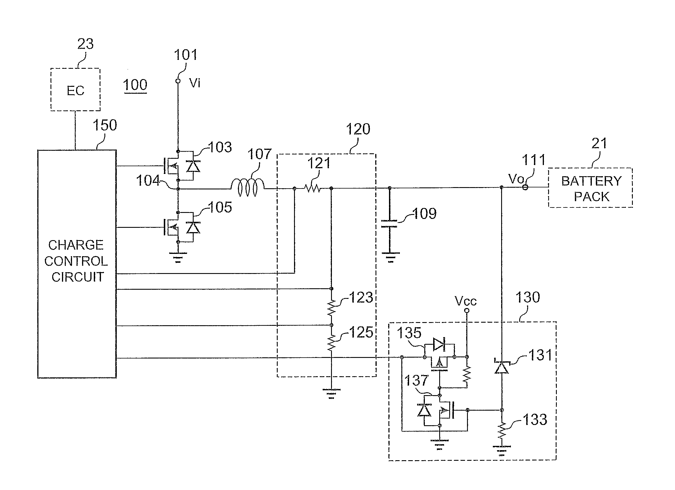
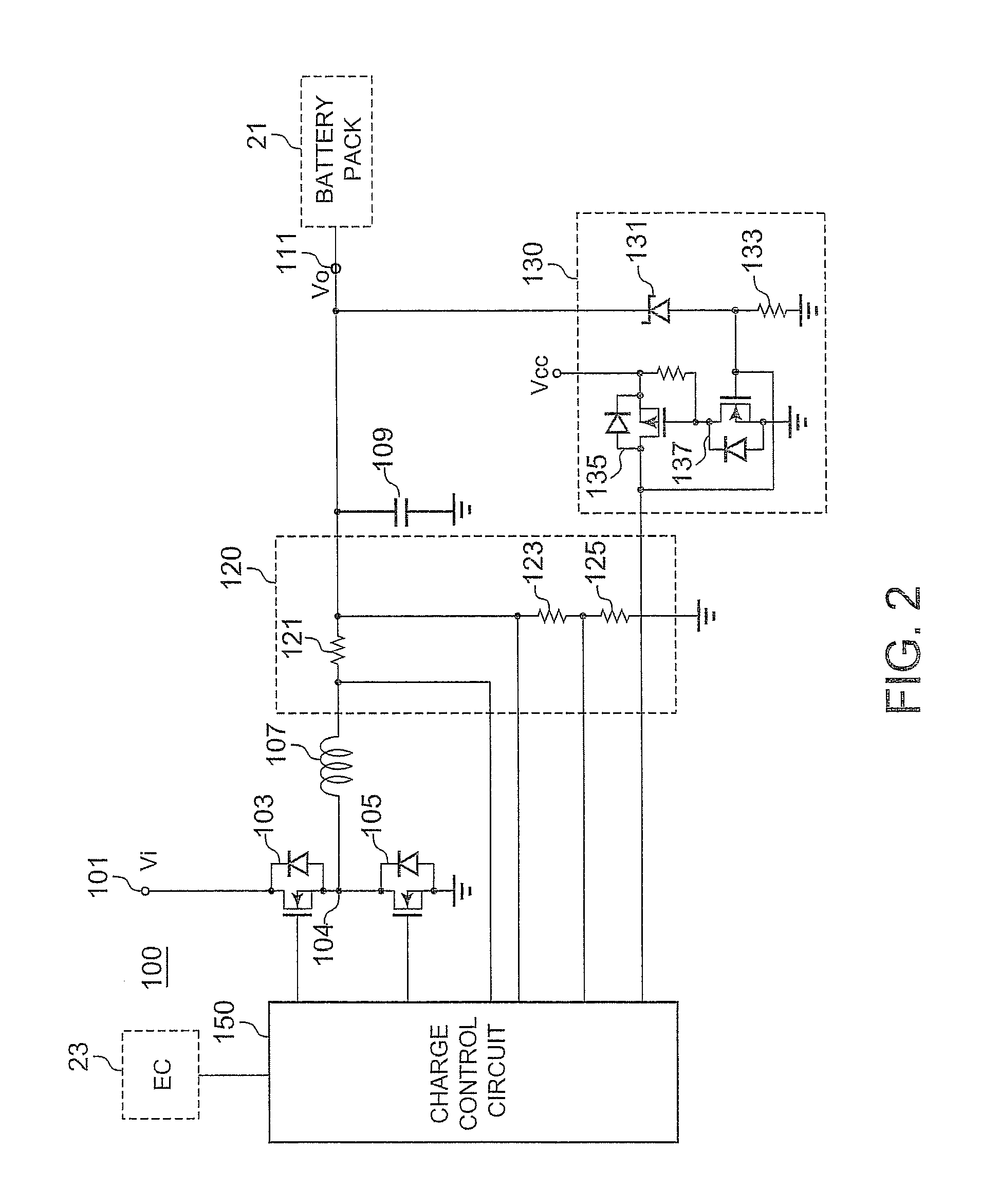
[0022]The EC 23 is a microcomputer made up of a CPU, a ROM, a RAM and the like, and further includes an A / D input terminal, a D / A output terminal, a timer and a digital input / output terminal of a plurality of channels. The EC 23 is connected with a battery pack 21, a charger 100 and a DC / DC converter 25 via signal lines. The EC 23 operates independently of the CPU 11 to control the operation of the DC / DC converter 25 so as ...


PUM


Abstract

A charge system is disclosed. A charge system includes a switching device and a controller. The switching device performs switching of a DC input voltage at a predetermined switching frequency to generate an output voltage, and the output voltage being utilized for charging said battery. The controller allows the switching device to operate at a first switching frequency immediately after starting of charge and at a second switching frequency when a frequency changing condition holds. The second switching frequency is higher than that of first switching frequency.

Description

PRIORITY CLAIM[0001]The present application claims benefit of priority under 35 U.S.C. §§120, 365 to the previously filed Japanese Patent Application No. JP2010-224851 entitled, “CHARGE SYSTEM AND CHARGE METHOD” with a priority date of Oct. 4, 2010, which is incorporated by reference herein.BACKGROUND[0002]1. Technical Field[0003]The present invention relates to battery chargers in general, and in particular to a method for suppressing heat generated by a semiconductor switch within a battery charger.[0004]2. Description of Related Art[0005]Battery chargers employed for charging a battery with a DC / DC converter generate a DC output voltage from a DC input voltage by controlling a semiconductor switching device such as a MOS-FET in a Pulse Width Modulation (PWM) manner or a Pulse Frequency Modulation (PFM) manner. Under PWM, the ON duration of a switching device is controlled so that a switching frequency as a function of a period corresponding to the total duration of the ON duratio...

Claims


Application Information

Patent Timeline
Patent Type & Authority Applications(United States)
IPC IPC(8): H02J7/00
CPCH02J7/045Y02B40/90Y02B70/1466H02M3/1588Y02B40/00Y02B70/10H02J7/04H02J7/00714H02J7/007182
Inventor ODAOHHARA, SHIGEFUMIWONG, TIN-LUPSEETHALER, KENNETH SCOTT
Owner LENOVO PC INT
Why Eureka
Try Eureka