Assembly for the selective three-dimensional or two-dimensional representation of images

Inactive Publication Date: 2012-04-05
TZSCHOPPE WOLFGANG +2
View PDF6 Cites 0 Cited by
  • Summary
  • Abstract
  • Description
  • Claims
  • Application Information

AI Technical Summary

Benefits of technology

[0024]Proceeding from this, it is the aim of the present invention to create an assembly of the aforesaid type that can be realized with simple means. The assembly should simultaneously provide several observers with a spatially perceptible image, without using ancillary equipment. It should be possible to display a high-resolution image, and most preferably a full-resolution image, in the 2-D mode. Furthermore, the image replication device that is the subject of this invention should also be able to satisfy the usual 3-D observation intervals even with a high resolution. Moreover, assemblies made according to the invention should exhibit the same ambient light suitability as is customary for 2-D displays of the same brightness.
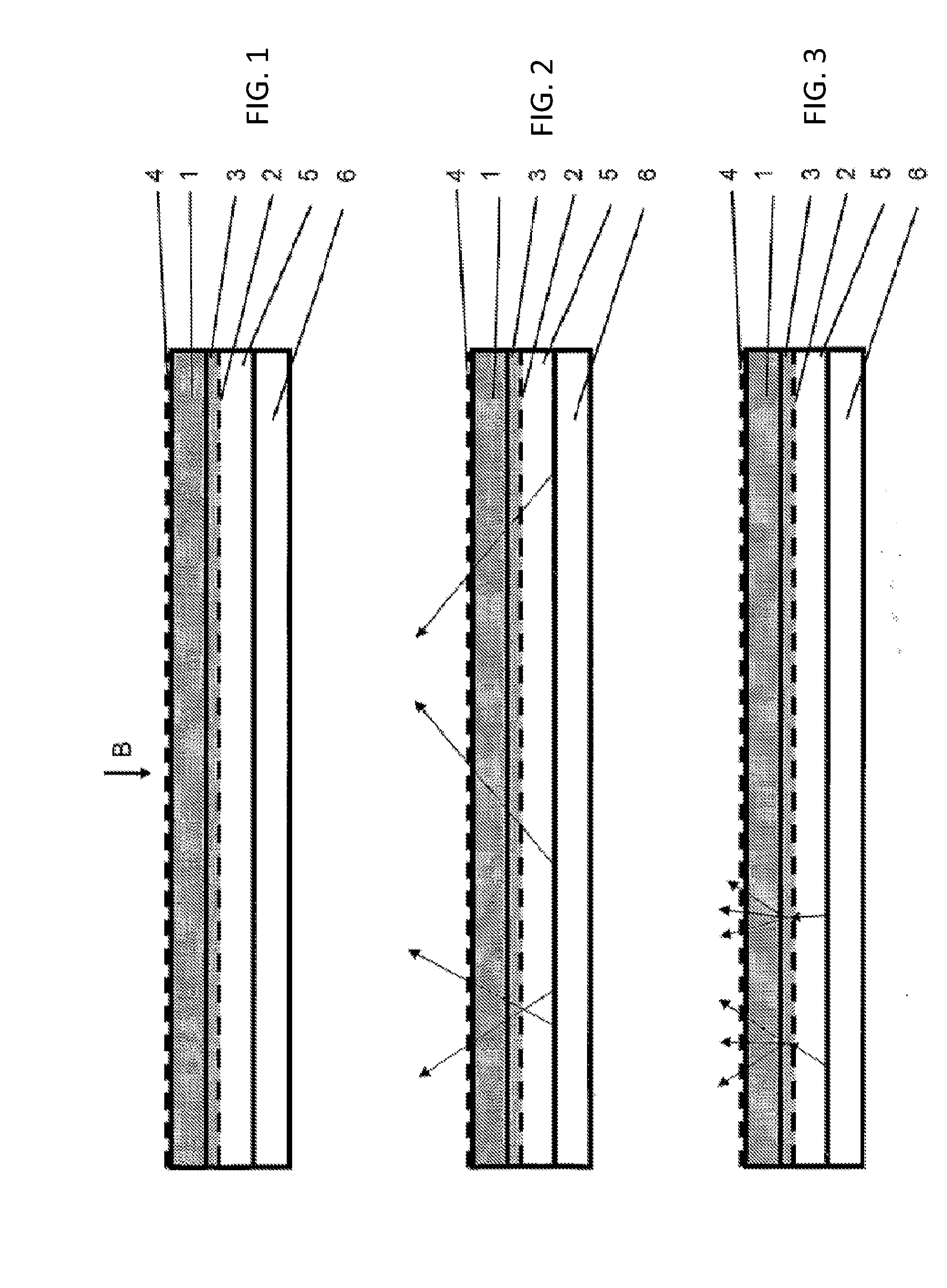
[0029]By way of contrast, the structuring of light penetrating through the filter array, with the first scattering layer in the dispersing state, is reduced with respect to the first state, and preferably beneath the contrast threshold for human sight, so that a two-dimensional image and / or full resolution text presented now is visible. According to the invention, the second scattering layer, which preferably exhibits an anti-glare matting, amplifies the aforesaid scattering effect in the line of sight of the viewer, directly on the image replication device, in this dispersing state. This characteristic of the assembly according to the invention has several advantages. For one thing, less demand need be made on the first scattering layer (in its dispersing state), i.e. solely a reduced haze value is necessary when compared with (notional) assemblies which are not provided with a second scattering layer.
[0030]However, the distance between the filter array and the first scattering layer can also be reduced (with undiminished first scattering layer haze in the scattering state), as the second scattering layer once again abolishes (disperses) any residual visibility of the filter array structure that may possibly occur because of the aforesaid reduction in spacing. Hence a lower structural depth of the assembly and also a smaller distance of the filter array from the image replication devices are possible. The latter is particularly advantageous if the usual viewing distances are to be realized with high-resolution image replication devices for the 3-D presentation.
[0035]This has the advantage that the image displayed to the viewer or viewers is of about the same brightness in both first layer states. The necessity of such a measure for changing the brightness arises from the fact that a spatial concentration of light occurs with different films (e.g. the Brightness Enhancement Film marketed by 3M) in many lighting instruments, which when in the dispersing state (but not in the transparent state) largely destroys the first scattering layer. This destruction of the spatial light concentration is accompanied by a reduction in average luminosity, since the available light is then distributed over a larger spatial angle.

Problems solved by technology

However, these assemblies often only permit a limited representation of ordinary text or two-dimensional images, as is the case e.g. with U.S. Pat. Nos. 4,457,574 and 5,606,455.
To be sure, the disadvantage here is that the light has to penetrate through two LCD panels, i.e. through a variety of components such as polarization filters, liquid crystal layers and further components such as carrier substrates, with the result that brightness is reduced both in the 2-D as well as the 3-D displays.
The disadvantage of this is that it is a two-channel 3-D display unit for only one observer who, in addition, has to take up a fixed position in order to make observations.
Furthermore, strong and disruptive moire effects are noticeable, if the observation positions chosen prior to the 3-D display are incorrect in their depth.
By the way, the device can only be manufactured at a high production engineering cost.
A further disadvantage is that the insertion of a switchable dispersing disk increases the distance between the illumination component and the image replication panel, which in particular prevents normal viewing distances in the case of 3-D displays with small pixel ratings and / or a high resolution.
Further disadvantages are sensitivity to dust and increased reflection losses.
The disadvantage here is that the 2-D light cannot be made sufficiently homogeneous with respect to the luminous density of the illumination.
Furthermore, when introducing a commercially available fiber-optic light guide as 2-D illumination, the macroscopic structure becomes visible to the observer or observers and a troublesome pattern emerges.
However, a microscopic structuring that is not visible is elaborate and expensive to manufacture.
The inherent disadvantage here is that a light source for parallel directional light is necessary so that, strictly speaking, no 3-D observation space can exist, but solely a single, fixed observation position.
Moreover, a complicated fiber-optic light guide is needed for parallel light radiation in the side light mode that is employed.
Likewise, a complicated and expensive side light would also be needed with any additional parallelization structure on the decoupling side opposite, i.e. for the area of the fiber-optic light guide on the observation side.
A disadvantage of this arrangement is that the resolution is very bad in the 2-D mode and that full resolution is not attained in the 2-D mode.
Such a lenticulation is, moreover, difficult and expensive to manufacture and has further disadvantages on account of the additional switchable dispersing properties.
The ambient light suitability of conventional 2-D displays is likewise not achieved.
Consequently, the scattering layer must degrade the 2-D image on the image transducer and cannot cancel the lenticular image-separating effect.
As a result, the text presented with these assemblies in 2-D mode also remains illegible; moreover, the ambient light suitability of conventional 2-D displays is not attained.

Method used


Image

  • Assembly for the selective three-dimensional or two-dimensional representation of images
  • Assembly for the selective three-dimensional or two-dimensional representation of images

Examples


Embodiment Construction

[0043]FIG. 1 illustrates the assembly according to the invention for the selective three-dimensional or two-dimensional representation of images, as a schematic diagram. The assembly comprises an image replicating device 1 with a multiplicity of image elements which in a predetermined co-ordination represent information from one or several aspects of a scene / of an object / of a text, a filter array 2 located behind the image replicating device 1, in the line of sight B of a viewer, which comprises a multiplicity of wavelength filter elements that are permeable to specific wavelength ranges, a first scattering layer 3 located behind the image replicating device 1 and in front of the filter array 2, in the line of sight B of the viewer, which can be selectively switched between a transparent state and a dispersing state, a second scattering layer 4 positioned in front of and directly on the image replicating device 1, in the line of sight of the viewer, which preferably corresponds to a...


PUM


Abstract

An assembly for two or three dimensional image representation having an image reproduction unit, a first scattering layer located behind the image reproduction unit in the line of vision of a viewer, a filter array located behind the image reproduction unit and the first scattering layer in the line of vision of a viewer, and a second scattering layer located in front of and directly on the image reproduction unit in the line of vision of the viewer. The first scattering layer has a plurality of image elements, which in a predetermined allocation represent information from one or more views of a scene, object or text and can be switched back and forth between a transparent condition and a scattering condition.

Description

CROSS-REFERENCE TO RELATED APPLICATIONS[0001]The present application is a continuation of U.S. Non-Provisional patent application Ser. No. 11 / 662,686 entitled “Assembly For The Selective Three-Dimensional Or Two-Dimensional Representation Of Images” filed by the present inventors on Feb. 25, 2008.[0002]The aforementioned non-provisional patent application is hereby incorporated by reference in its entirety.BACKGROUND OF THE INVENTION[0003]1. Field of the Invention[0004]The present invention relates to an assembly for the selective three-dimensional or two-dimensional representation of images.[0005]2. Brief Description of the Related Art[0006]A multiplicity of methods and assemblies has been developed during the course of research in the field of automatic stereoscopic display, which convey spatial impressions to one or more observers without the need for ancillary equipment. However, these assemblies often only permit a limited representation of ordinary text or two-dimensional imag...

Claims


Application Information

Patent Timeline
IPC IPC(8): G06T15/00
CPCH04N13/0454H04N13/359H04N13/00
Inventor TZSCHOPPE, WOLFGANGKLIPPSTEIN, MARKUSBRUGGERT, THOMAS
Owner TZSCHOPPE WOLFGANG
Why Eureka
Try Eureka