Electrofluidic imaging film, devices, and displays, and methods of making and using the same

a technology of electro-fluidic imaging and film, applied in the field of electro-fluidic, can solve the problems of reducing affecting the optical performance of the display, so as to reduce or eliminate the need for precise electrode alignment, simple fabrication methods, and the effect of eliminating the optical loss associated with pixel border features

Active Publication Date: 2012-04-05
UNIVERSITY OF CINCINNATI
View PDF3 Cites 47 Cited by
  • Summary
  • Abstract
  • Description
  • Claims
  • Application Information

AI Technical Summary

Benefits of technology

[0005]The present invention relates to electrofluidic imaging films, or devices, that overcome the issues with conventional devices by reducing or eliminating the need for precise electrode alignment to a particular pixel, allowing for simple fabrication methods, and providing imaging or information display without the optical losses associated with pixel border features.
[0009]In one embodiment of the present invention, a method of fabricating a display pixel includes fabricating first and second electrodes on first and second substrates, respectively. A film is positioned between the first and second electrodes on the first and second substrates and the substrates are secured to create a fluid space. First and second fluids are dosed into different portions of the fluid space. The film is porous to at least one of the first and second fluids. At least one spacer is located within the fluid space to support the film and to also facilitate movement of the first fluid in a manner that causes the second fluid to split.

Problems solved by technology

If the fluids from adjacent pixels join, then it may be difficult and unpredictable to split the fluids and to return the fluid to the respective pixel.
Un-even splitting of the fluids will cause excess fluid to build up in some pixels and reduce the optical performance of the display.
In some cases, un-even fluid splitting may continue until display operation is no longer possible.
Furthermore, when features are formed around the border of adjacent pixels to keep the fluids of the adjacent pixels separated, these features take up visible space and reduce the optical performance of the display.

Method used


Image

  • Electrofluidic imaging film, devices, and displays, and methods of making and using the same
  • Electrofluidic imaging film, devices, and displays, and methods of making and using the same
  • Electrofluidic imaging film, devices, and displays, and methods of making and using the same

Examples


example 1

[0082]The display performance with respect to the various embodiments of the present invention may be calculated for pixel densities ranging from about 1 pixel-per-inch (“PPI”) to about 1000 PPI. A review of performance requirements for devices is provided in J. HEIKENFELD, et al., “A critical review of the present and future prospects for electronic paper,”J. Soc. Inform. Display. 19(2):129-156 (2011). Table 1 includes calculations made using proven models for electrofluidic transport, including light outcoupling losses, and are benchmarked off actual data measured for 25 PPI pixels (see Example 3). It is clear that various devices in accordance with one or more embodiments of the present invention may satisfy bill-board application pixel resolutions (1 PPI) and speeds (300 PPI) where video rate (<20 ms) speed is required.

[0083]In terms of optical performance, several comparisons may be made. Firstly, the present invention is nearly twice as reflective as the E INK (E Ink Co., Camb...

example 2

[0084]Two display devices were fabricated in a manner as described in S. YANG, et al., “High reflectivity electrofluidic pixels with zero-power grayscale operation,”Appl. Phys. Lett. 97(14): 143501-143503 (2010).

[0085]The first device was fabricated in the exact same manner described in the reference, but without spacers in the upper channel. When tested, the polar fluid merged between pixels in the upper channel and could not be returned to the lower channel. The merging and degradation of the display device worsened over time.

[0086]The second device was fabricated in the exact same manner described in the publication, but without aligning the channels to the segmented electrodes on the lower substrate. Pixels partially spanning the edges of the segmented electrodes only partially operated or failed to operate because of the lack of alignment with a complete electrode.

example 3

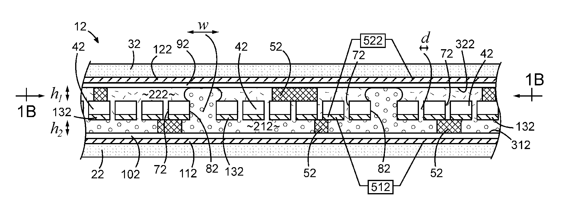
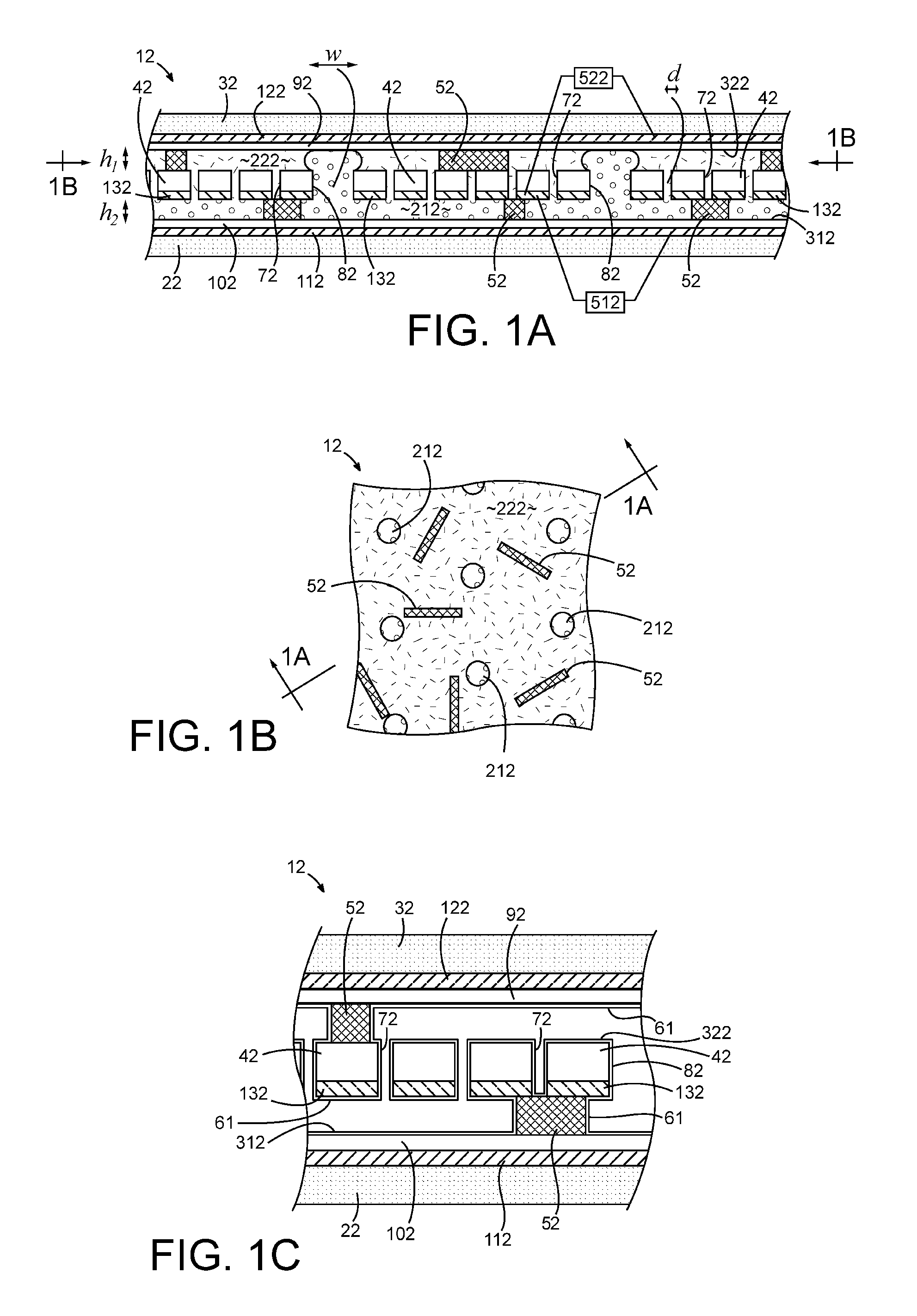
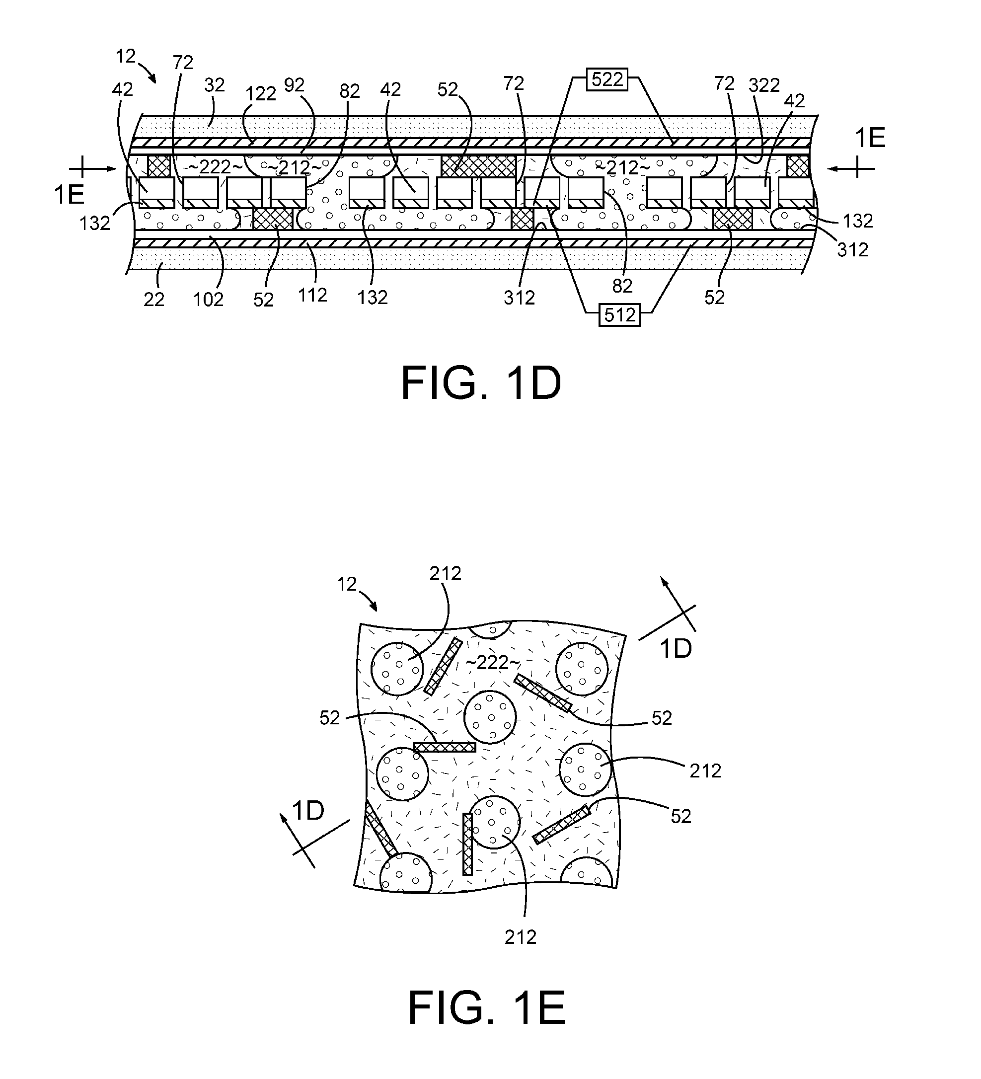
[0087]Devices were fabricated from multiple 6 inch polycarbonate porous films, which were obtained from Structure Probe, Inc. (West Chester, Pa.) with small 10 μm diameter pores and a pore density of 8×10⁵ per square inch. A low cost CO2 laser-engraving machine was then used to mill into the film an array of larger 100 μm pores in a hexagonal lattice having a lattice constant of about 500 μm. This porous film was then sputter coated with about 100 nm of reflective and conductive Al. The film was then dip-coated in diluted Cytonix 1601V fluoropolymer solution and baked at 50° C. to form a 50 nm thick non-electrically-insulating hydrophobic coating. One of two 6 inch glass substrates was patterned with various segmented and transparent In2O3:SnO2 electrode test patterns, patterned with 50 μm thick and 200 μm long spacers, insulated with 1 μm of Parylene C dielectric, and similarly coated with fluoropolymer. The other one of the two 6 inch glass substrates was formed in a manner simila...


PUM

PropertyMeasurementUnit
thicknessaaaaaaaaaa
Young's wetting angleaaaaaaaaaa
AC voltageaaaaaaaaaa

Abstract

A device and method of making and using the same. The device includes first and second substrates that are spaced to define a fluid space. Polar and non-polar fluids occupy the fluid space. A first electrode, with a dielectric layer, is positioned on the first substrate and electrically coupled to at least one voltage source, which is configured to supply an electrical bias to the first electrode. The fluid space includes at least one fluid splitting structure that is configured to facilitate the movement of the non-polar fluid into a portion of the polar fluid. Fluid splitting structure assisted movement of the non-polar fluid splits the polar fluid.

Description

CROSS-REFERENCE TO RELATED APPLICATIONS[0001]This application claims the benefit of U.S. Provisional Application No. 61 / 388,272, filed Sep. 30, 2010, the disclosure of which is hereby incorporated by reference herein in its entirety.STATEMENT REGARDING FEDERALLY SPONSORED RESEARCH OR DEVELOPMENT[0002]The U.S. Government has a paid-up license in this invention and the right, in limited circumstances, to require the patent owner to license others on reasonable terms as provided for by the terms of Grant No. 0640964 awarded by the National Science Foundation and Grant No. W9111NF-09-2-0034 awarded by the U.S. Army Research Labs.BACKGROUND[0003]Conventional electrofluidic displays are capable of transposing one or more colored fluids through microfluidic cavities using electrowetting control. The technology is capable of higher brightness and improved color saturation as compared to some electrowetting or electrophoretic displays. Unlike electrophoretic displays, where exact pixel and s...

Claims


Application Information

Patent Timeline
Patent Type & Authority Applications(United States)
IPC IPC(8): G02B26/00H01J9/00
CPCY10T29/49124Y10T29/49117G02B26/004Y10T29/49826G02B26/005
Inventor HEIKENFELD, JASONHAGEDON, MATTHEWANDREW, KENNETH DEAN
Owner UNIVERSITY OF CINCINNATI
Why Eureka
Try Eureka