
Low Power Radio Controlled Clock Incorporating Independent Timing Corrections

a radio controlled clock and independent technology, applied in the field of wireless communication, can solve the problems of inaccuracy, few parts per million (ppm) to 20 ppm, and wide availability of low-cost crystals, and achieve the effects of reducing duty cycles, shortening battery life, and minimizing the energy associated with wireless reception

Inactive Publication Date: 2012-04-05
GRINDSTONE CAPITAL
View PDF0 Cites 21 Cited by
  • Summary
  • Abstract
  • Description
  • Claims
  • Application Information

AI Technical Summary

Benefits of technology

"The present invention provides a system and method for compensating for the natural drift that occurs in a radio-controlled clock (RCC) type timekeeper due to its inaccuracy. The invention allows the RCC to operate at reduced duty-cycles, minimizing energy consumption and extending battery life. The invention includes a communication protocol that allows prior-art devices to operate in accordance with the legacy communication protocol, while still being affected by the natural drift. The invention uses a known barker code and coding techniques to detect and correct errors in the received signal. The invention also takes into account the timekeeper's ability to estimate the drift and adjust its timing accordingly. The invention can be applied to battery-operated devices, such as wristwatches, and can provide a warning when the drift exceeds a certain threshold. The invention allows for periodic corrections based on the estimated drift, reducing energy consumption and improving accuracy."

Problems solved by technology

These widely available low-cost crystals, however, may experience inaccuracies that range from a few parts per million (ppm) to ±20 ppm, depending on again effects and the temperature range in which they operate.

Method used


Image

  • Low Power Radio Controlled Clock Incorporating Independent Timing Corrections
  • Low Power Radio Controlled Clock Incorporating Independent Timing Corrections
  • Low Power Radio Controlled Clock Incorporating Independent Timing Corrections

Examples


Embodiment Construction

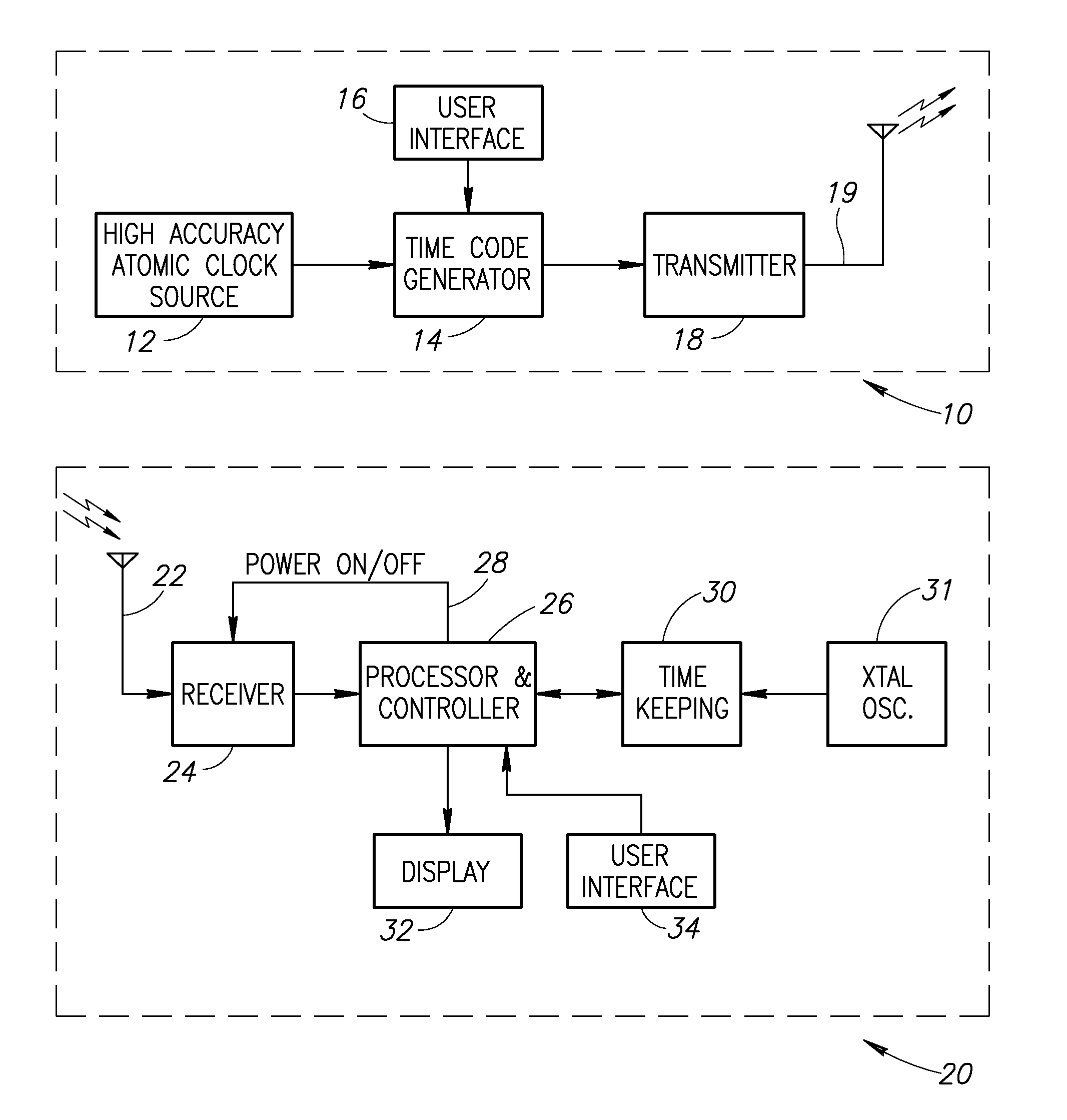
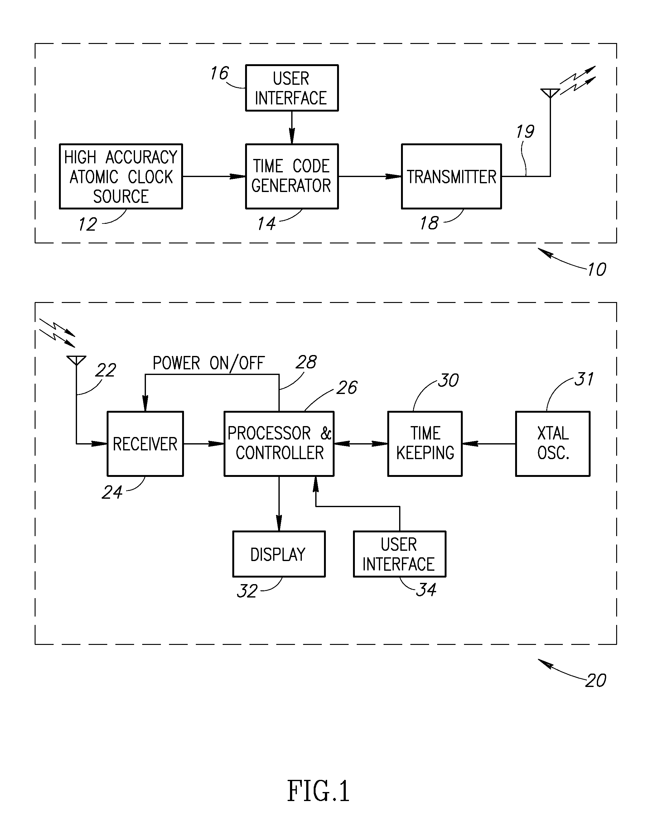
[0028]A block diagram illustrating an example high-level description of a system operating in accordance with the present invention is shown in FIG. 1. The equipment at the transmitter end, generally referenced 10, comprises a high accuracy frequency source 12 from which a clock signal is derived, a time-code-generator 14 having user-interface 16, a transmitter 18 and a transmitting antenna 19.

[0029]The time code generator 14 keeps track of time based on the high-accuracy frequency source input to it from source 12, constructs the frames of data representing the time information and other information that is to be transmitted, modulates the data frames onto the RF carrier in accordance with protocol of the present invention and allows time initialization and other controls to be set in it through its user interface 16. The transmitter 18 amplifies the modulated signal to the desired levels, e.g., 50 kW, and drives the antenna 19 that is used for the wide-coverage omnidirectional bro...


PUM


Abstract

A timekeeping device that tracks the time provided by a digital broadcast and the protocol of that broadcast, defined by its data frame structure and modulation scheme, are adapted to allow for superior performance of the timekeeping devices in terms of range of operation, immunity to interference, ability to operate with lower cost antennas due to enhanced link robustness, and reduced energy consumption. The timekeeping device operates with infrequent receptions of the broadcast by relying on independent self-compensation. This alleviates the need for frequent receptions to ensure timing accuracy while reducing energy consumption. The mean and variability of successive measurements of timing drift are evaluated and an estimated upper bound for the drift-estimation error is set. Based on this bound, the device employs a reception strategy that relies on less frequent receptions, corresponding to the error in estimating the drift rather than to the magnitude of the drift itself

Description

REFERENCE TO PRIORITY APPLICATION[0001]This application claims priority to U.S. Provisional Application Ser. No. 61 / 385,167, filed Sep. 22, 2010, entitled “A Reduced-Cost Enhanced-Performance System for Broadcasting and Receiving an Atomic Clock Timing Signal,” incorporated herein by reference in its entirety.FIELD OF THE INVENTION[0002]The present invention relates to the field of wireless communications, and more particularly relates to a timekeeping device capable of compensating for its inherent inaccuracy by synchronizing with a wirelessly received signal in a power-efficient and reliable manner.BACKGROUND OF THE INVENTION[0003]A radio-controlled-clock (RCC) is a timekeeping device that provides the user with accurate timing information that is derived from a received signal, which is broadcast from a central location, to allow multiple users to be aligned or synchronized in time. Colloquially, these are often referred to as “atomic clocks” due to the nature of the source used ...

Claims


Application Information

Patent Timeline
Patent Type & Authority Applications(United States)
IPC IPC(8): G04C11/02
CPCH04W56/0035Y02B60/50G04R20/12G04R40/06Y02D30/70
Inventor ELIEZER, OREN E.AWASTHI, ADITYA
Owner GRINDSTONE CAPITAL
Learn More