Control apparatus for autonomous operating vehicle

a technology for controlling apparatus and operating vehicle, applied in process and machine control, distance measurement, instruments, etc., can solve the problems of increasing cost and complicated structure, and achieve the effect of increasing cost, complicated structure, and improving work efficiency

Active Publication Date: 2012-04-05
HONDA MOTOR CO LTD
View PDF4 Cites 65 Cited by
  • Summary
  • Abstract
  • Description
  • Claims
  • Application Information

AI Technical Summary

Benefits of technology

[0006]Although the techniques in '812 and '738 enable to detect the border of the travel-scheduled area, it is preferable to additionally detect a position of the operating vehicle in the detected area for improving the work efficiency. Although the GPS signal is used in '136 to deal with it, it makes the structure complicated and may lead to the increase in cost, disadvantageously.
[0007]An object of the invention is therefore to overcome the foregoing drawback by providing an apparatus for controlling an autonomous operating vehicle that can detect a border of an operating (travel-scheduled) area and a position of the vehicle in the area with the simple structure.

Problems solved by technology

Although the GPS signal is used in '136 to deal with it, it makes the structure complicated and may lead to the increase in cost, disadvantageously.

Method used


Image

  • Control apparatus for autonomous operating vehicle
  • Control apparatus for autonomous operating vehicle
  • Control apparatus for autonomous operating vehicle

Examples


first embodiment

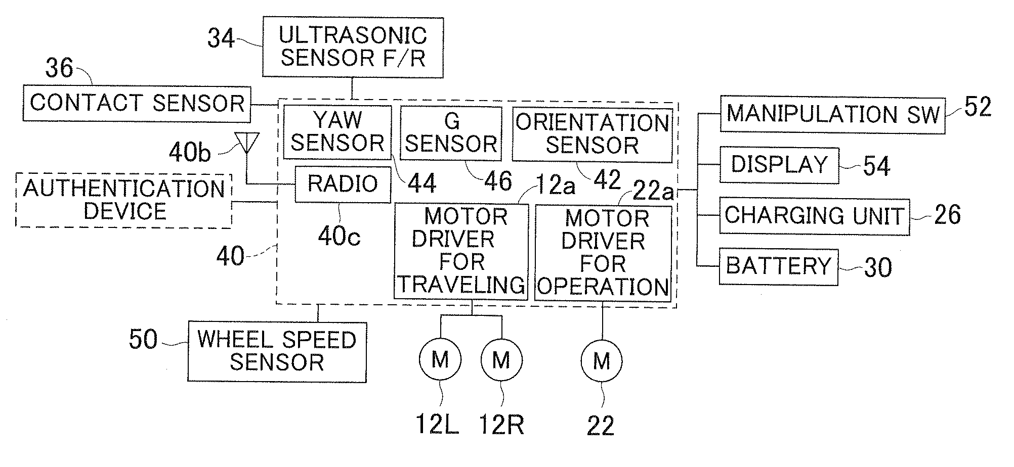
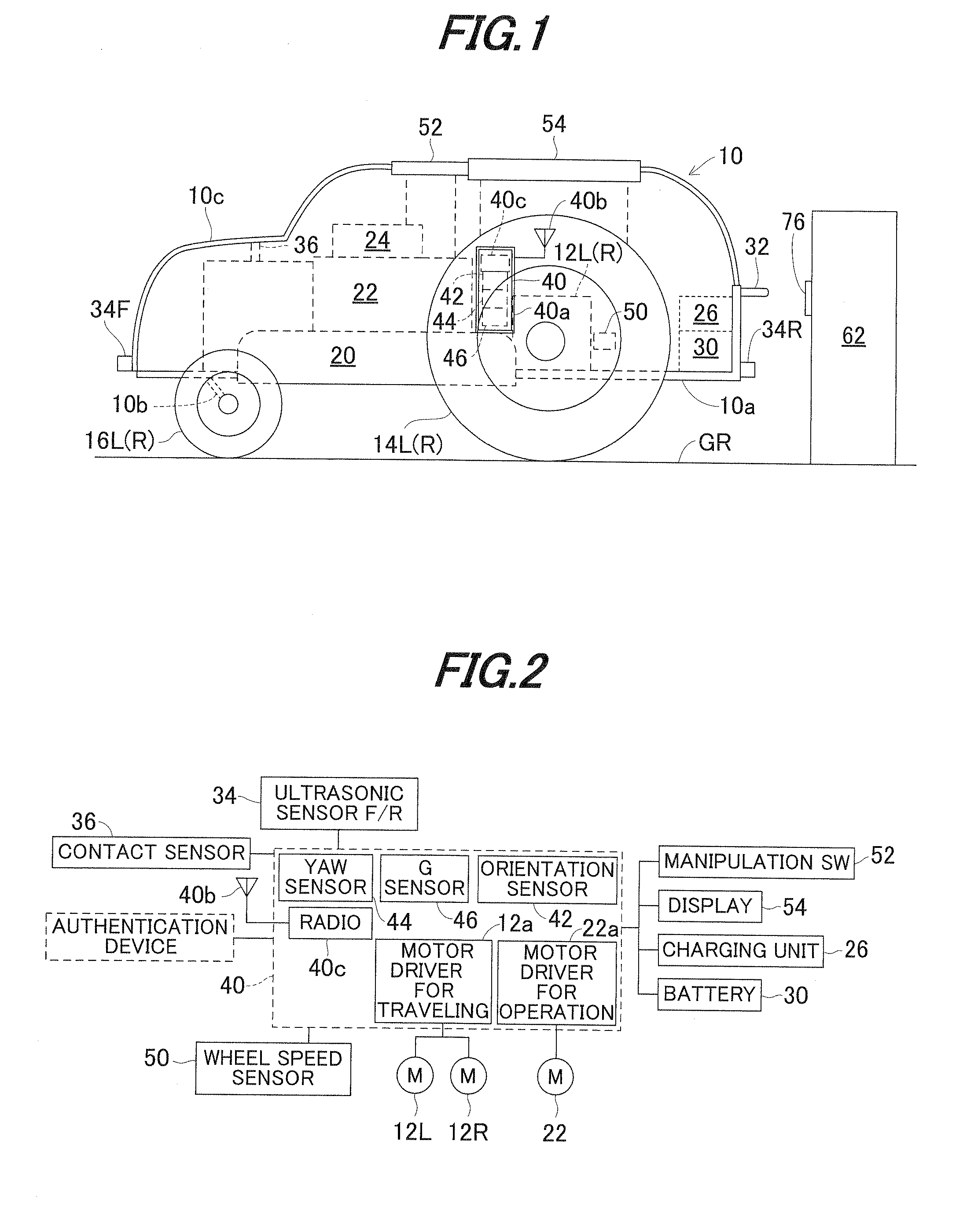
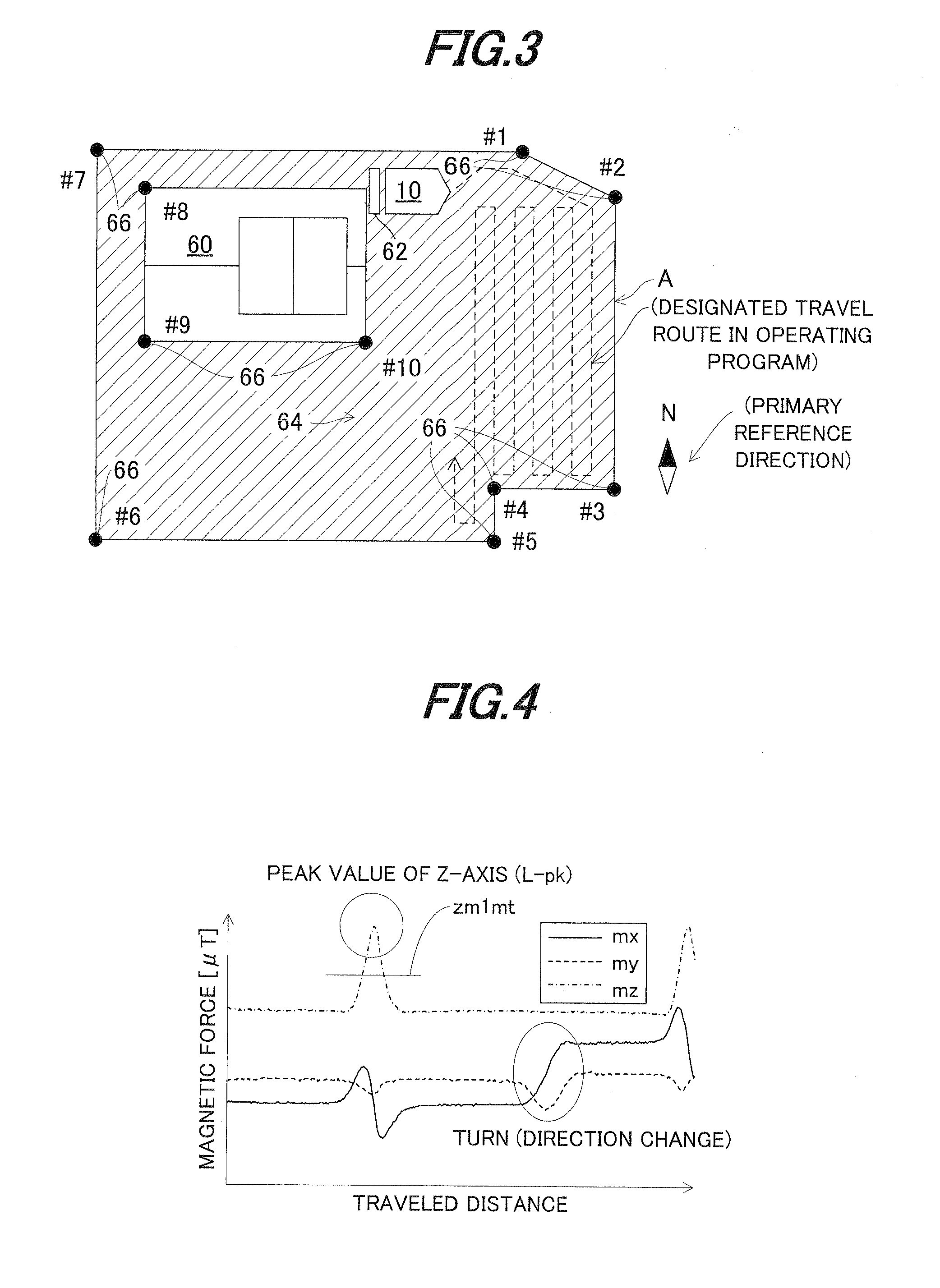
[0034]FIG. 1 is an overall schematic view of a control apparatus for an autonomous operating vehicle according to the invention, FIG. 2 is a block diagram showing input and output of sensors, an electronic control unit (ECU), electric motors (prime movers), etc., mounted on the vehicle, FIG. 3 is a plan view showing an operating (travel-scheduled) area where the vehicle of FIG. 1 is to be traveled, FIG. 4 is a waveform diagram showing triaxial outputs of an orientation sensor (geomagnetic sensor) shown in FIG. 1, FIG. 5 is an explanatory view showing charging operation at a charge station shown in FIG. 1, FIG. 6 is a block diagram showing the configuration of the charge station shown in FIG. 5, FIG. 7 is a block diagram showing the configuration of manipulation equipment used by an operator for the vehicle shown in FIG. 1, FIG. 8 is a block diagram functionally showing the operation of the apparatus (ECU) shown in FIG. 2 and FIG. 9 is an explanatory view of map information shown in ...

second embodiment

[0093]FIG. 14 is a flowchart showing the operation of a control apparatus for an autonomous operating vehicle 10 according to the invention.

[0094]The apparatus according to the second embodiment is configured so that, in the travel control of the vehicle 10, the ECU 40 corrects the traveling direction calculated based on the output of the Yaw sensor 44 with the primary reference direction detected through the processing of S104 in the FIG. 11 flowchart.

[0095]Specifically, since the travel-scheduled area A is not necessarily flat, i.e., could have uneven parts, slopes or slippery parts, and sampling time of the Yaw sensor outputs is limited, they may cause an error in the calculated traveling direction. The second embodiment is given to deal with it.

[0096]The program begins in S300, in which a turning command is sent to the motor 12 through the driver 12a and the program proceeds to S302, in which the vehicle 10 is turned by a desired angle (1) (e.g., 30 degrees).

[0097]Next the progr...

third embodiment

[0101]As shown in FIG. 15, when a device 90 such as an outdoor unit of an air conditioner, which could cause magnetic field distortion, exists in the travel-scheduled area A, the output of the orientation sensor 42 is influenced thereby and distorted. The third embodiment is given to deal with it.

[0102]The explanation will be made with reference to FIG. 17. The program begins in S400, in which the travel (operation) of the vehicle 10 is continued and proceeds to S402, in which it is determined whether a change arises in geomagnetic data detected by the orientation sensor 42.

[0103]When the result in S402 is affirmative, the program proceeds to S404, in which it is determined whether no turning command is sent and when the result in S404 is affirmative, the program proceeds to S406, in which it is determined whether there is magnetic field variation data, i.e., whether a device 90 which could cause magnetic field distortion exists in the travel-scheduled area A.

[0104]When the result i...


PUM


Abstract

In an apparatus for controlling an autonomous operating vehicle having a prime mover and operating machine, it is configured to have a geomagnetic sensor responsive to magnets embedded in the area, detect angular velocity generated about z-axis in center of gravity of the vehicle, detect a wheel speed of the driven wheel, store map information including magnet embedded positions, detect a primary reference direction, detect a vehicle position relative to the magnet, and detect a vehicle position in the area, calculate a traveling direction and traveled distance of the vehicle, and control the operation performed through the operating machine in the area in accordance with a preset operation program based on the detected primary reference direction, the detected position of the vehicle in the area, the calculated traveling direction and the calculated traveled distance.

Description

BACKGROUND[0001]1. Technical Field[0002]The invention relates to a control apparatus for an autonomous operating vehicle, particularly to a control apparatus for a vehicle that autonomously travels to perform work or operation, e.g., mow lawn.[0003]2. Background Art[0004]In an autonomous operating vehicle that autonomously travels to perform work or operation such as mowing lawn in a defined operating (travel-scheduled) area it is necessary to detect a border of the area. Therefore, magnets are embedded on the border and a sensor sensing the magnets is mounted on the vehicle to detect the border, as taught, for example, by Japanese Laid-Open Patent Application No. Sho 60(1985)-239812 ('812).[0005]Japanese Laid-Open Patent Application No. Hei 8(1996)-286738 ('738) discloses a technique to embed an electric wire along the border and detect generated magnetic field by a sensor mounted on an operating vehicle, thereby detecting the border. Further, Japanese Patent No. 3467136 ('136) pro...

Claims


Application Information

Patent Timeline
Patent Type & Authority Applications(United States)
IPC IPC(8): G01C21/34
CPCG05D1/0261G05D1/027G05D1/0225G05D1/0274G05D2201/0208G05D1/0272
Inventor SATO, KAZUHISAYAMAMURA, MAKOTOMASUBUCHI, YOSHINORI
Owner HONDA MOTOR CO LTD
Why Eureka
Try Eureka