
Method for operating an aerosol inhalation device and aerosol inhalation device

a technology of aerosol inhalation and air, which is applied in the direction of respiratory masks, transportation and packaging, respirators, etc., can solve the problems of only achieving the effect of improving the retention of drugs in the nose, affecting the quality of life and daily functioning, and large portions of the nasal cavity that are not exposed, so as to reduce the risk of occurrence, reduce the dead space within the device, and improve the efficiency of the aerosol transport process

Active Publication Date: 2012-04-12
PARI PHARMA GMBH +1
View PDF8 Cites 28 Cited by
  • Summary
  • Abstract
  • Description
  • Claims
  • Application Information

AI Technical Summary

Benefits of technology

[0009]In a first aspect, the invention provides a method for operating an aerosol inhalation device, comprising the steps of transporting a certain amount of an aerosol to a desired location outside said device and vibrating the transported aerosol when it has reached said desired location. Preferably, the transported aerosol is vibrated only when it has reached said desired location. As used herein, the term “vibration (pulsation, pressure oscillation) of an aerosol” is understood as a periodic change of pressure that occurs at a predetermined frequency. Preferably, the vibration is regular, i.e., the time interval between pressure peaks is approximately constant. The amplitude of the vibrations may also be substantially constant. By vibrating the aerosol at a given frequency, aerosol diffusion can be significantly enhanced, enabling improved access to locations that are difficult to reach with a constant pressure aerosol flow, such as the paranasal sinuses. Additionally, pressure differences between nasal and sinus cavity effectuates an airflow and with it, ventilation of the sinuses. The principle of applying a vibrating aerosol for enhanced sinus deposition has recently been found and is described, for example, in WO 2004 / 020029.
[0091]In one embodiment, the desired location is the nasal cavity or the mucosa in the nose and the inhalation device of the invention further comprises a sensor and control element configured to allow actuation of the vibrator for vibrating the aerosol only during a period of exhalation through the nasal cavity. As discussed above, by allowing actuation of the vibrator for vibrating the aerosol only during a period of exhalation through the nasal cavity, the ventilation of the paranasal sinuses is improved, resulting in an even more efficient deposition of the flowed aerosol in the paranasal sinuses. By using a sensor and control element for automatically triggering the aerosol vibration step, the aerosol deposition process can be carried out in a well-defined and controlled manner without the need for any coordination efforts from the patient.

Problems solved by technology

These conditions may be associated with significant symptoms and have a negative impact on quality of life and daily functioning.
However, studies investigating the in vivo deposition pattern of droplets administered by a spray pump indicate that local distribution is primarily in the anterior portion of the nasal cavity leaving large portions of the nasal cavity unexposed to drug (see Suman et al., “Comparison of nasal deposition and clearance of aerosol generated by a nebulizer and an aqueous spray pump”, Pharmaceutical Research, Vol. 16, No. 10, 1999).
However, those attempts were only successful to improve retention of drugs in the nose prolonging the residence time, the time to clear 50% of dose, up to 2.2 hours.
Consequently, the effective treatment of the nasal and paranasal mucosa via a method to increase residence time remains challenging.
While the mucosa of the nasal cavity is a feasible target for locally administered drugs formulated as nasal sprays, the sinuses and the osteomeatal complex are not easily accessed by liquid formulations.
Nevertheless, it is still only a fraction of any aerosol which can be delivered to the sinunasal target area by the methods known today.
Furthermore, there exists a problem in known methods that the pressure oscillations or vibrations superimposed on the main aerosol flow lead to an increased aerosol impaction on the walls of the aerosol generator and / or the nostril entry, resulting in a reduced aerosol output and consequently a less efficient therapeutic treatment.

Method used


Image

  • Method for operating an aerosol inhalation device and aerosol inhalation device
  • Method for operating an aerosol inhalation device and aerosol inhalation device
  • Method for operating an aerosol inhalation device and aerosol inhalation device

Examples


Embodiment Construction

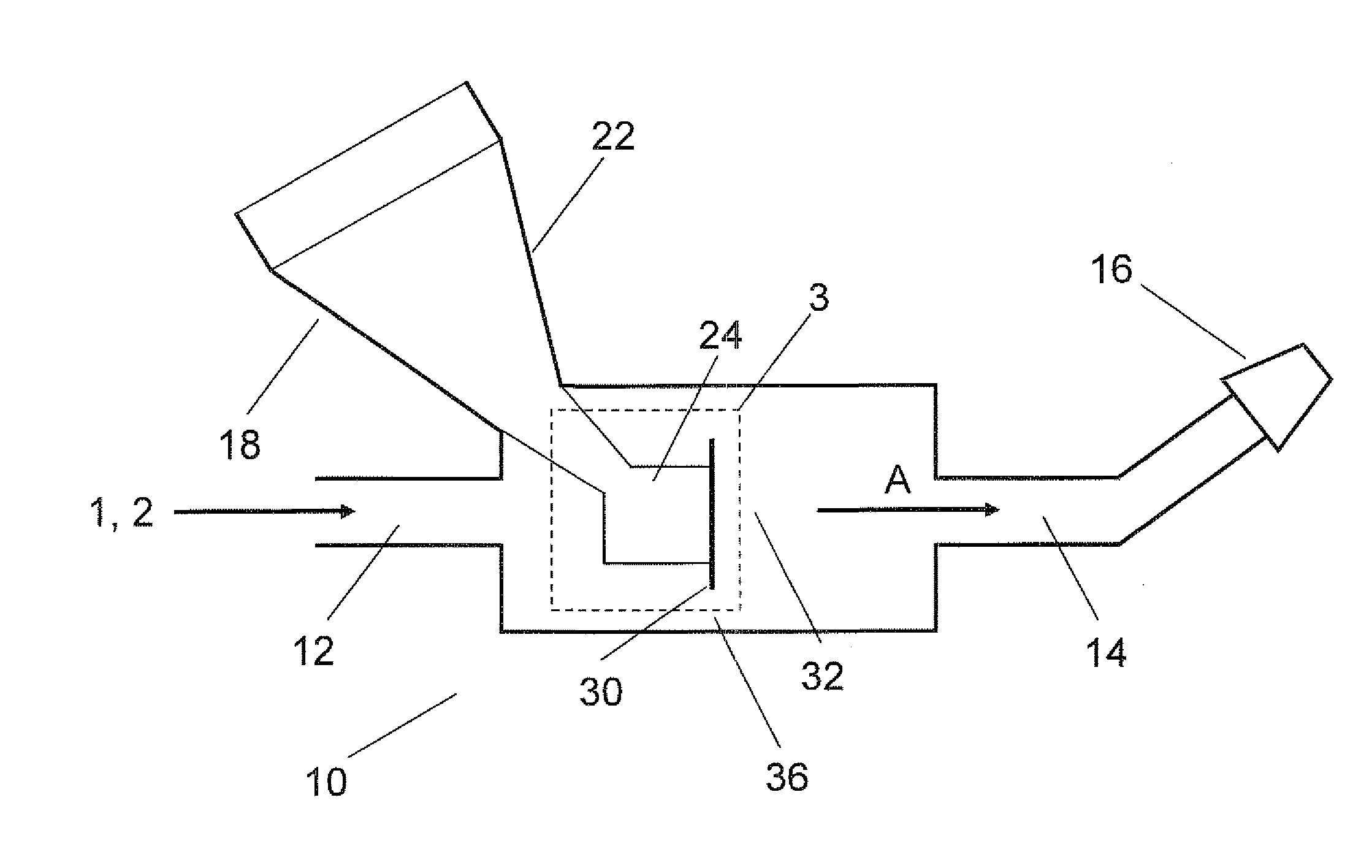
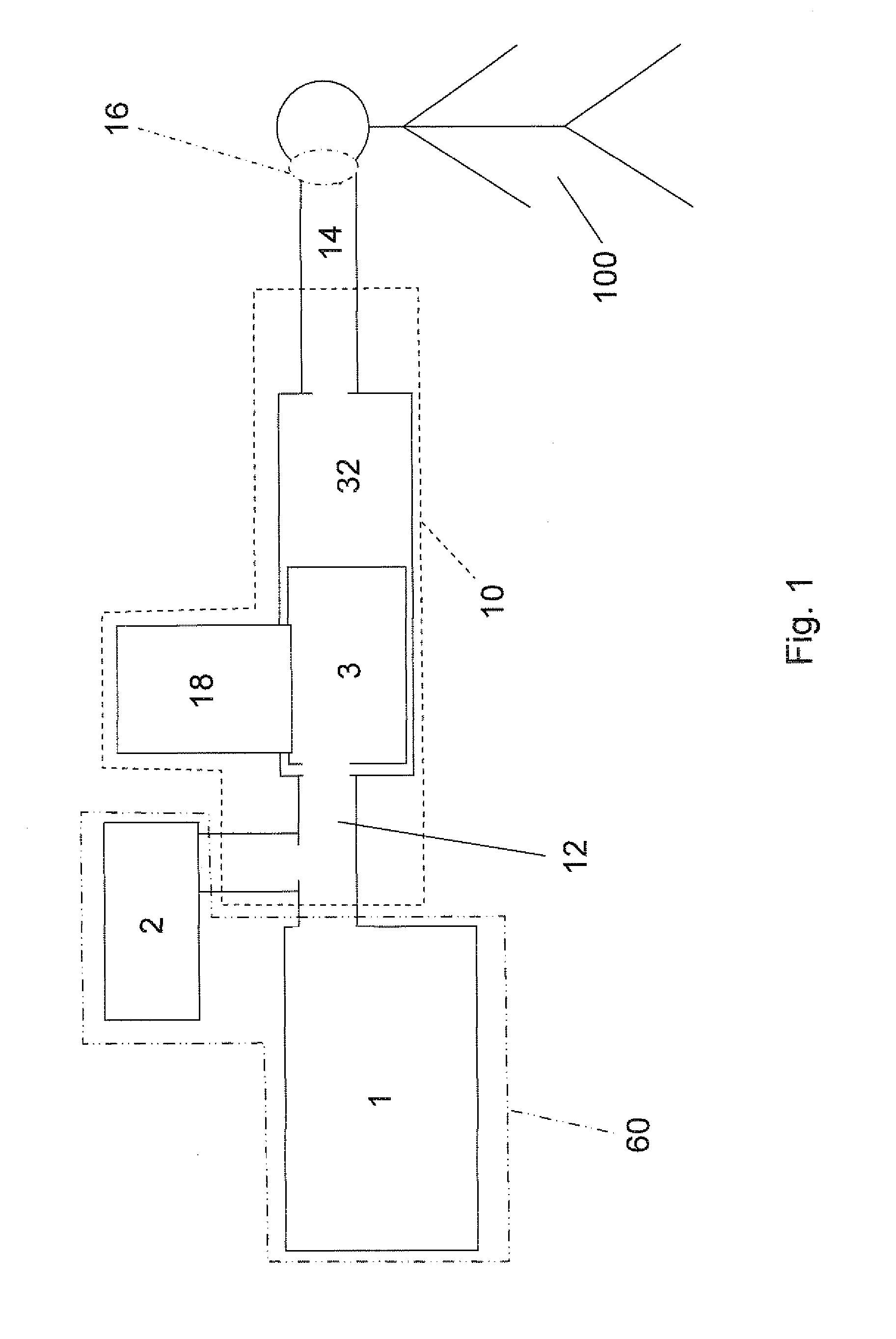
[0103]FIGS. 1 to 4 show schematic views of aerosol inhalation devices 10 according to currently preferred embodiments of the present invention.

[0104]The aerosol inhalation device 10 contains an aerosol generator 3, which may be an inhaler, atomiser or nebuliser, especially a nebuliser of the ultrasonic, jet or electro hydrodynamic type, Metered Dose Inhaler (MDI), Dry Powder Inhaler (DPI), spinning disc, and / or a nebuliser operating with a vibrating membrane or with pores of defined size.

[0105]As can be seen from FIGS. 1 to 4, the aerosol inhalation device 10 according to the currently preferred embodiments comprises a connector 12 for connection with a gas compressor 1 as a source of compressed air and an adaptation element 14 that is equipped with a nosepiece 16 or an optional mouthpiece 50 for adaptation to (communication with) a patient's 100 respiratory system, nasal cavity etc. A fluid container 18 for receiving a fluid to be nebulised is disposed between connector 12 and adap...


PUM


Abstract

In a first aspect, the invention relates to a method for operating an aerosol inhalation device (10), comprising the steps of transporting a certain amount of an aerosol to a desired location outside said device (10) and vibrating the transported aerosol when it has reached said desired location. In a second aspect, the invention relates to an aerosol inhalation device (10) comprising a pump (1) for flowing a certain amount of an aerosol to a desired location outside the device (10), a vibrator (2) for vibrating the transported aerosol in a vibration mode and a control configured to actuate the vibrator (2) for vibrating the flowed aerosol only when it has reached said desired location.

Description

FIELD OF THE INVENTION[0001]The invention relates to a method for operating an aerosol inhalation device (nebuliser) and an aerosol inhalation device implementing this method.BACKGROUND ART[0002]Diseases and conditions affecting either paranasal sinuses or both the nasal cavity and the paranasal sinuses, in particular acute and chronic forms of rhinosinusitis, are increasing in incidence and prevalence in many countries and regions of the world, including Europe and the United States. These conditions may be associated with significant symptoms and have a negative impact on quality of life and daily functioning.[0003]The method most commonly used to deliver medications to the nasal cavity is a squeeze bottle or a metering spray pump nebulising volumes of 50 to 140 μl per actuation. However, studies investigating the in vivo deposition pattern of droplets administered by a spray pump indicate that local distribution is primarily in the anterior portion of the nasal cavity leaving lar...

Claims


Application Information

Patent Timeline
IPC IPC(8): A61M16/10A61M16/06A61M11/04A61M11/00A61M15/00
CPCA61M2205/3386A61M15/0085
Inventor LUBER, MARTINBOEHM, ANDREASSCHUSCHING, UWEKRUENER, AXEL
Owner PARI PHARMA GMBH
Learn More