Method For Antenna Calibration In A Wideband Communication System

Inactive Publication Date: 2012-04-12
HIGHBRIDGE PRINCIPAL STRATEGIES LLC AS COLLATERAL AGENT
View PDF3 Cites 54 Cited by
  • Summary
  • Abstract
  • Description
  • Claims
  • Application Information

AI Technical Summary

Benefits of technology

[0011]An object with the present invention is to provide a method for antenna calibration in a wideband communication system communicating

Problems solved by technology

However, due to mechanical and electrical variations in the RF components, such as amplifiers, mixers and cables, that occur over time due to temperature variations, aging, and other factors, the spatial signature of the baseband receive/transmit signal is significantly different from the actual RF receive/transmit signal.
As mentioned above, the bandwidth in LTE is significantly wider than in previous wireless standards, such as WCDMA, and this makes it difficult to ensure that the overall

Method used


Image

  • Method For Antenna Calibration In A Wideband Communication System
  • Method For Antenna Calibration In A Wideband Communication System
  • Method For Antenna Calibration In A Wideband Communication System

Examples


first embodiment

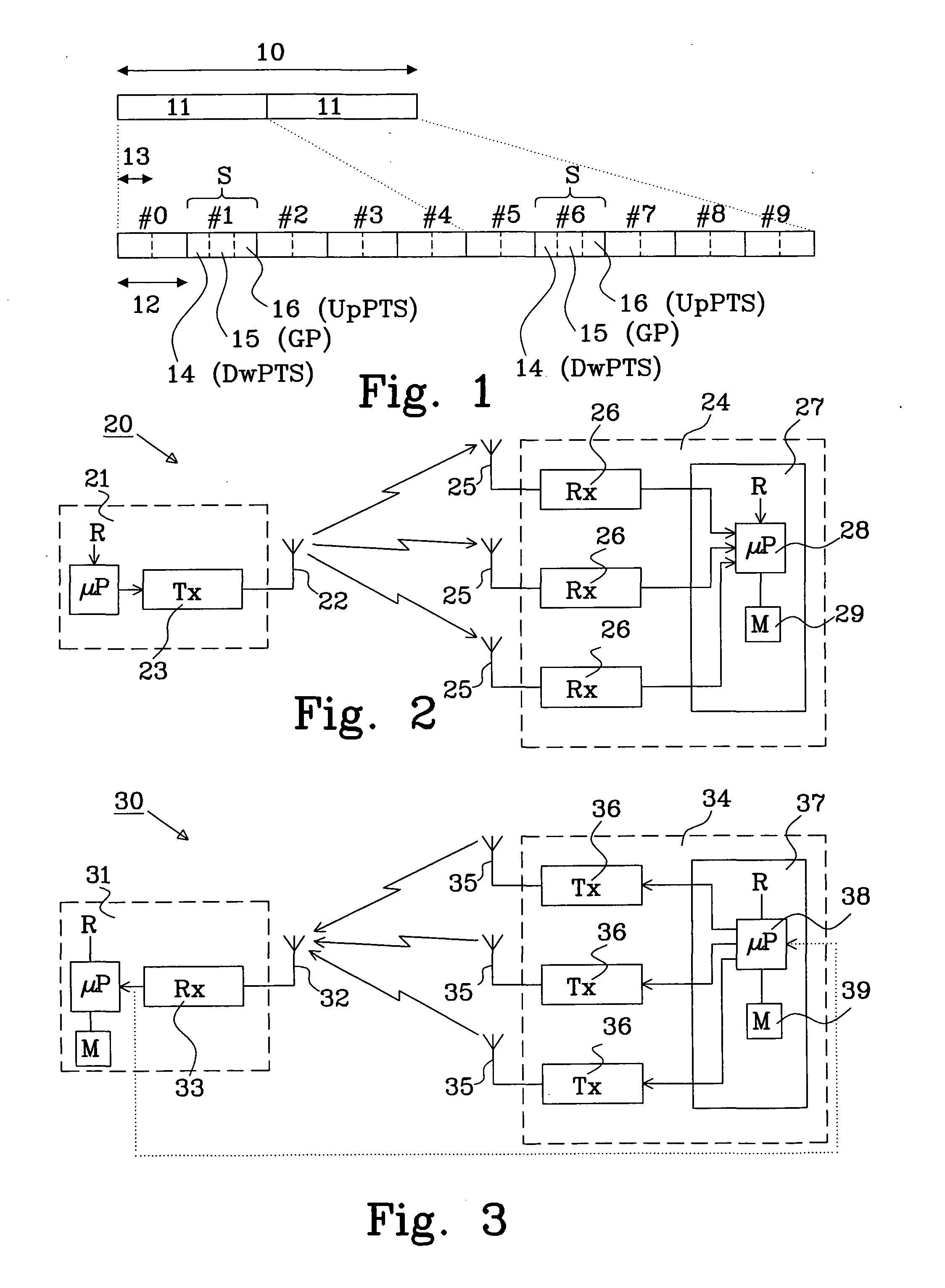
[0047]FIG. 2 shows a communication system 20 comprising a transmission part 21 and a receiver part 24. The transmission part 21 comprises in this example of a single antenna 22 coupled to a transmission (Tx) chain 23 coupled to a micro processor μP. A reference sequence indicated by “R” is accessible to the μP which feeds the reference sequence to the Tx chain for transmission via the antenna 22. The receiver part 24 comprises in this example of three antennas 25; each coupled to an individual reception (Rx) chain 26; and a processing unit 27. The processing unit comprises a processor (μP) 28 having access to the reference sequence “R” transmitted from the transmission part 21, and a memory (M) 29.

[0048]The actual process of calibrating the antennas in the receiver part 24 is known to a skilled person and could be summarized as follows. The reference sequence “R” is fed to the Tx chain 23 and transmitted from antenna 22 and thereafter received by the three antennas 25, processed by ...

second embodiment

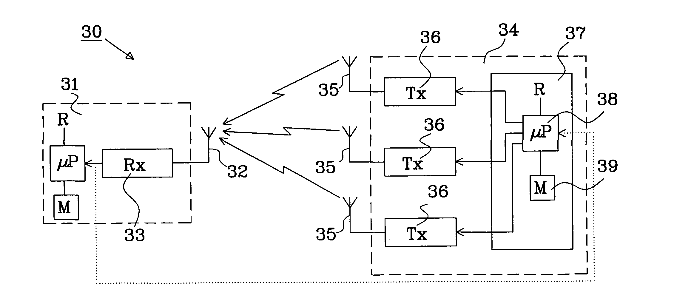
[0050]FIG. 3 shows a communication system 30 comprising a receiver part 31 and a transmission part 34. The receiver part 31 comprises in this example of a single antenna 22 coupled to a reception (Rx) chain 33. Optionally, the receiver part 31 may include a micro processor μP and a memory M. The transmission part 34 comprises in this example of three antennas 35, each coupled to an individual transmission (Tx) chain 36; and a processing unit 37. The processing unit 37 comprises a processor μP 38, a memory (M) 39.

[0051]The actual process of calibrating the antennas in the transmission part 34 is similar to the process described above. The reference sequence R, which is accessible to the μP 38 is fed to each Tx chain 36 to be transmitted from each corresponding antenna 35 in the transmission part 34. Three signals are received by the single antenna 32 in the receiver part 31 and are processed by the Rx chain 33 and the received signal is then forwarded to the μP 38 for further process...


PUM


Abstract

The present invention relates to a method for antenna calibration in a communication system having a bandwidth divided into multiple frequency intervals M with multiple communication units 40; 50, each comprising communication circuitry 21, 24: 31, 34; 41, 42; 51, 52, 54 connected to an antenna arrangement 22, 25; 32, 35; 44, 45; 55, 49, communicating with each other over multiple communication channels. The method comprises: establishing a calibration sequence to perform antenna calibration for at least one of said multiple frequency intervals; converting the calibration sequence from the frequency domain to the time domain; transmitting a part of said calibration sequence in the time domain from a first communication circuitry 21; 34; 41; 51, 54 to a second communication circuitry 24; 31; 42; 52, 54 over the multiple communication channels; receiving the part of said calibration sequence in the second communication circuitry 24; 31; 42; 52, 54 for each communication channel; performing antenna calibration based on the received part of the calibration sequence.

Description

TECHNICAL FIELD[0001]The present invention relates to a method for antenna calibration in a wideband communication system, wherein two communication units communicate over multiple communication channels. The invention also relates to a system, and a communication unit.BACKGROUND[0002]Wideband communication systems, such as the LTE-TDD system, have a significantly wider bandwidth than in previous wireless standards, e.g. U-TRAN supports a bandwidth of 5 MHz. The LTE-TDD system supports the application of multiple antenna techniques, e.g. MIMO and beam forming as disclosed in reference [1]. A base station system using an adaptive beam forming algorithm is expected to increase its maximum range and capacity due to an improved antenna gain and the reduction of interference from other spatially separated users. E.g. an antenna array having M antenna elements may, in principle, provide a mean power gain of M over white noise. Beam forming algorithm normally assumes that the antenna array...

Claims


Application Information

Patent Timeline
IPC IPC(8): H04W72/04H04J11/00
CPCH01Q3/267H04B7/0413H04B17/21H04B17/0085H04B17/11H04B17/0062
Inventor GUO, YUXINLIAO, JINGYI
Owner HIGHBRIDGE PRINCIPAL STRATEGIES LLC AS COLLATERAL AGENT
Why Eureka
Try Eureka