Method of clamping fuel cell stack

a fuel cell and stack technology, applied in the field of clamping fuel cell stacks, can solve the problems of difficult to diffuse gas, difficult to maintain even pressure over the entire stack area, etc., and achieve the effect of increasing contact resistance and lowering clamping pressur

Inactive Publication Date: 2012-04-12
HYUNDAI MOTOR CO LTD
View PDF1 Cites 6 Cited by
  • Summary
  • Abstract
  • Description
  • Claims
  • Application Information

AI Technical Summary

Benefits of technology

[0030]Embodiments of the present invention provide a method of clamping a fuel cell stack that may stably and optimally clamp the stack without any problems, such as an irreversible variation in thickness of a gas diffusion layer, a lowering in clamping pressure, creation of a tiny gap, an increase in contact resistance, etc., while the stack is operated.
[0042]According to the embodiments of the present invention, the method of clamping a fuel cell stack performs a process of correcting a variation in clamping pressure after the preliminary clamping and pre-treatment process of the stack, and thus, may stably and optimally clamp the stack without any problems, such as an irreversible variation in thickness of a gas diffusion layer, a lowering in clamping pressure, creation of a tiny gap, an increase in contact resistance, etc., while the stack is operated.

Problems solved by technology

In a case where the surface pressure is too high, the gas diffusion layer is excessively compressed making it difficult to diffuse a gas.
Accordingly, if a thickness of the gas diffusion layer, which is a component of the stack, is decreased during the operation, a surface pressure distribution is changed in the unit cell, and this makes it difficult for an even pressure to be maintained over the entire area of the stack.

Method used


Image

  • Method of clamping fuel cell stack
  • Method of clamping fuel cell stack
  • Method of clamping fuel cell stack

Examples


Embodiment Construction

[0053]Hereinafter, exemplary embodiments of the present invention will be described with reference with the accompanying drawings.

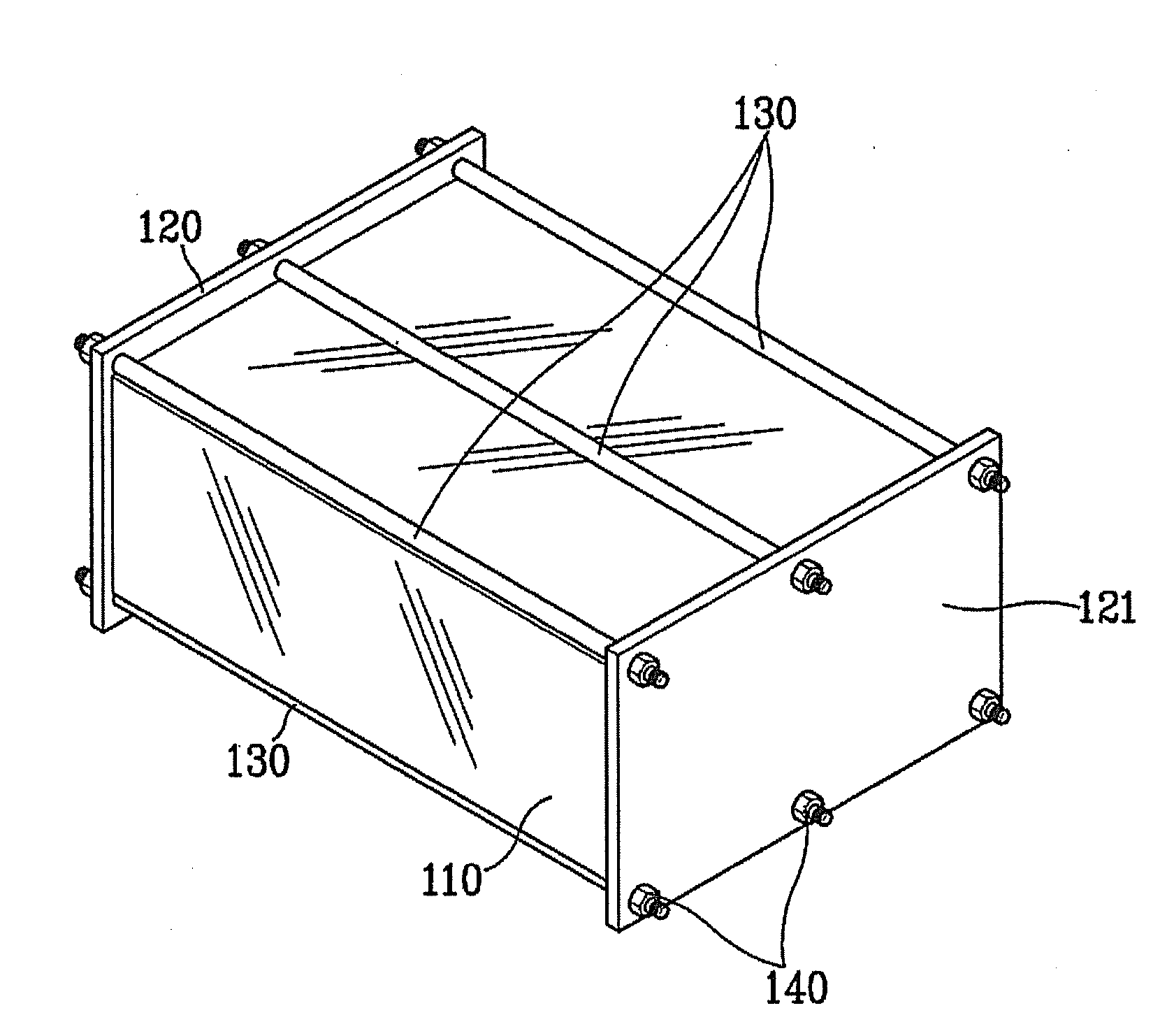
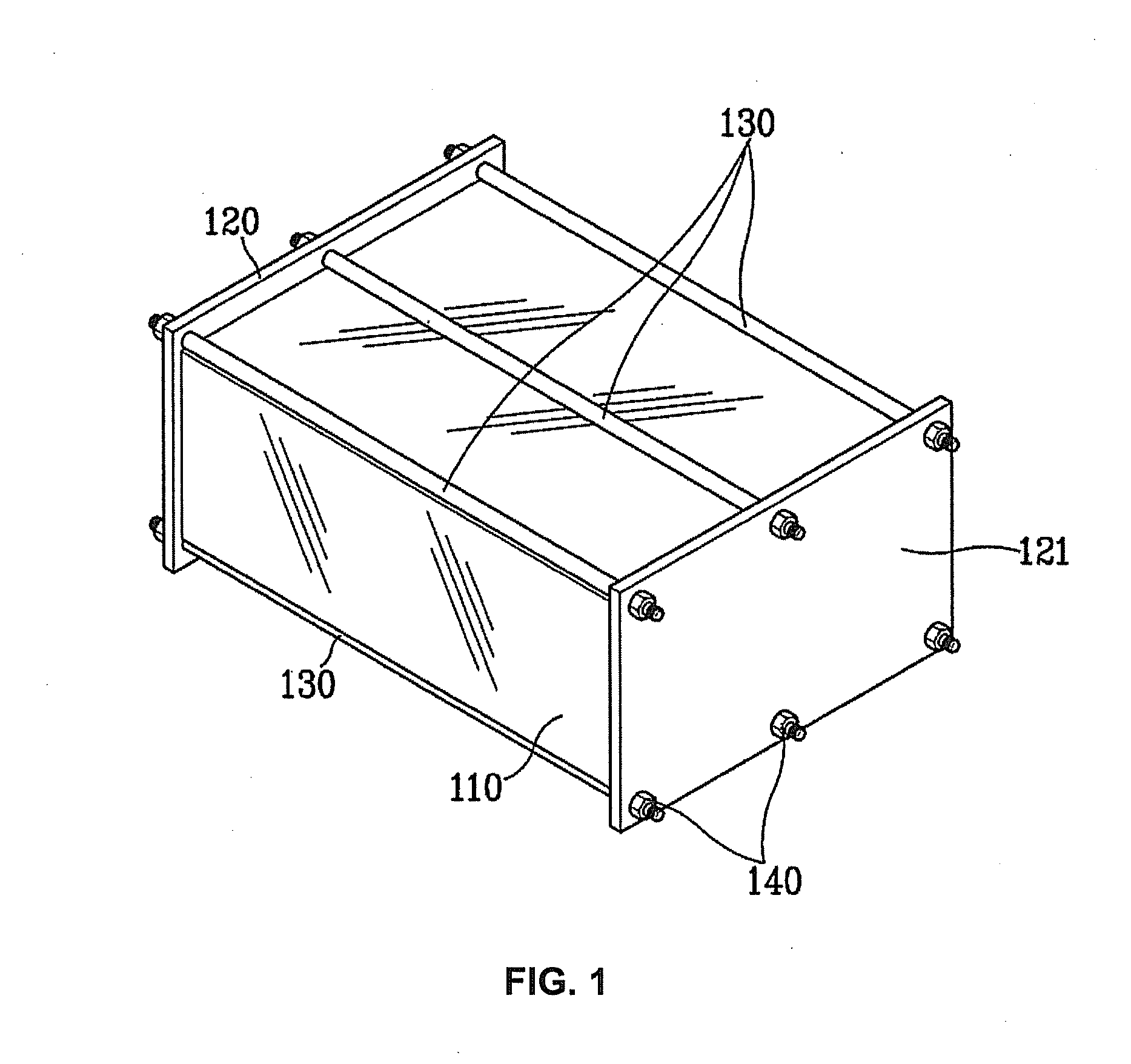
[0054]As described above, a few tens to a few hundreds of unit cells are stacked on one another and end plates are joined on the ends thereof. Then, the end plates are clamped by a long bolt (clamping rod), a band, or a wire, so that a uniform pressure is exerted over the entire area of the MEA of each cell.

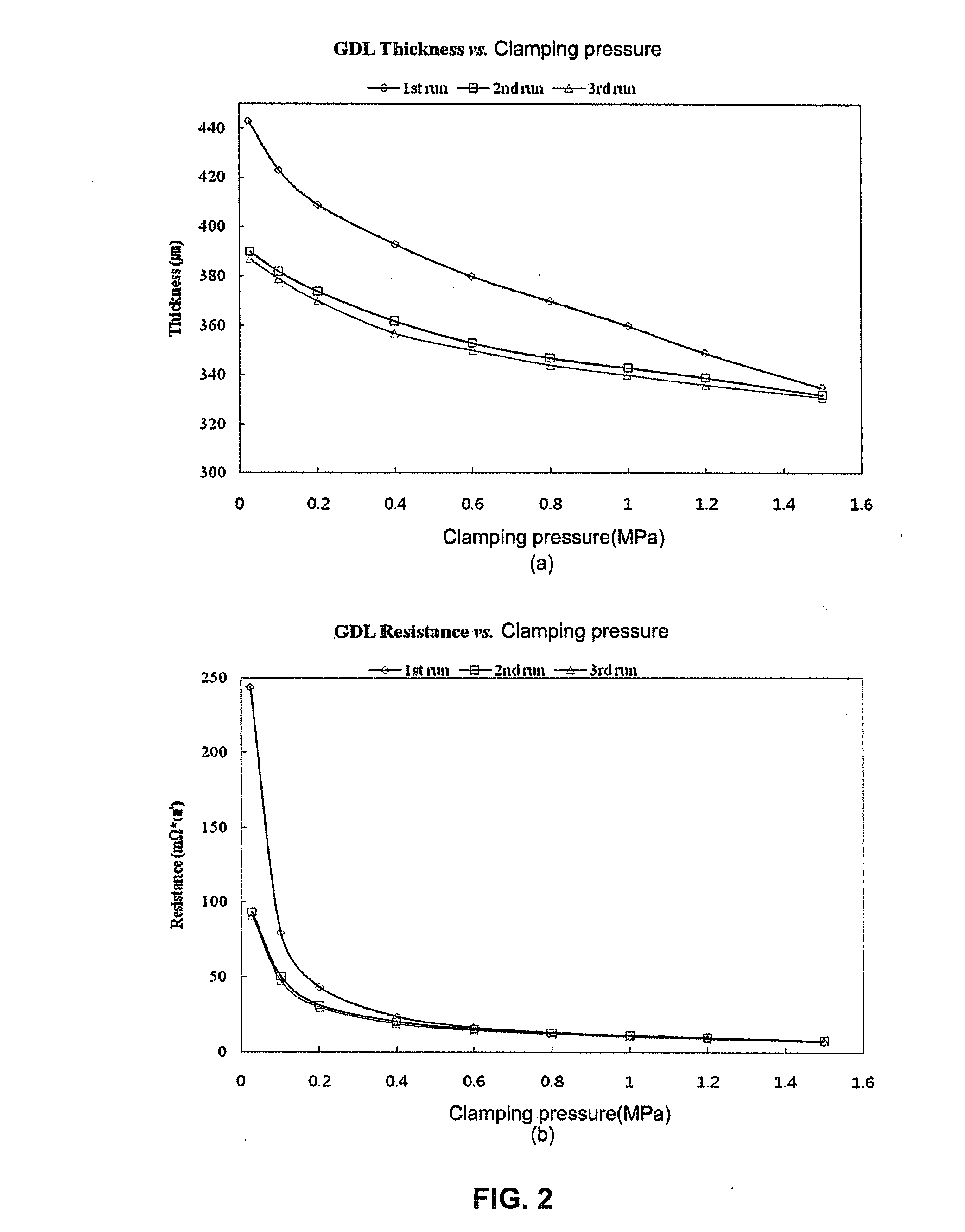
[0055]The bipolar plate, the gasket, and the MEA have high elasticity, and their thickness is reversibly changed with the clamping pressure. However, the gas diffusion layer is mainly made of a porous carbon support for purposes of smooth diffusion of a reaction gas and dehydration. Accordingly, the gas diffusion layer experiences an irreversible change in thickness depending on a variation in clamping pressure.

[0056]Thus, if the clamping pressure is changed due to vibration occurring during the stack operation, with the stack size remaining unchanged ...


PUM

PropertyMeasurementUnit
temperatureaaaaaaaaaa

Abstract

A method of clamping a fuel cell stack includes a stack preliminary clamping step, a stack pre-treatment step of performing a gas flow rate variation cycle or a clamping pressure variation cycle, wherein the gas flow rate variation cycle repeatedly changes a flow rate of a gas supplied to an anode and a cathode included in the preliminarily clamped stack, and wherein the clamping pressure variation cycle repeatedly increases and decreases the clamping pressure by pressurization and pressure release of the preliminarily clamped stack using the pressure tool, and a stack main clamping step of correcting a variation in clamping pressure occurring due to a variation in thickness of a gas diffusion layer to mainly clamp the stack after the stack pre-treatment step.

Description

CROSS-REFERENCE TO RELATED APPLICATION[0001]This application claims the benefit of Korean Patent Application No. 10-2010-0098509, filed on Oct. 8, 2010, under 35 U.S.C. §119(a). The entire contents of the aforementioned application are incorporated herein by reference.BACKGROUND[0002](a) Technical Field[0003]The present disclosure is directed to a method of clamping a fuel cell stack, and more specifically, to a method of clamping a fuel cell stack that may clamp the stack in a stable and optimal manner without any problems, such as an irreversible variation in thickness of a gas diffusion layer, a lowering in clamping pressure, creation of a tiny gap, an increase in contact resistance, etc., while the stack is operated.[0004](b) Background Art[0005]A fuel cell is an energy converting device that converts the chemical energy of a source fuel into electric energy through an electrochemical reaction, without a process of converting the source fuel into heat by combustion. Fuel cells m...

Claims


Application Information

Patent Timeline
Patent Type & Authority Applications(United States)
IPC IPC(8): H01M8/24
CPCH01M8/04089H01M8/04753Y02E60/50H01M2008/1095H01M8/248
Inventor KWAK, BU HOHONG, BO KIHAN, KOOK ILPARK, JI YEON
Owner HYUNDAI MOTOR CO LTD
Why Eureka
Try Eureka