
On-chip helix antenna

a technology of patch antenna and antenna, applied in the field of antenna, can solve the problems of large size of on-chip patch antenna, 77 ghz, and only 5 dbi gain performan

Active Publication Date: 2012-04-19
TAIWAN SEMICON MFG CO LTD
View PDF10 Cites 36 Cited by
  • Summary
  • Abstract
  • Description
  • Claims
  • Application Information

AI Technical Summary

Problems solved by technology

However, for a conventional patch antenna for millimeter wave communication, the performance is an issue with about only 5 dBi gain.
Also, the large size of the on-chip patch antenna (e.g., 1.18 mm×0.89 mm for a 77 GHz application) and the antenna cost are problematic.

Method used


Image

  • On-chip helix antenna
  • On-chip helix antenna
  • On-chip helix antenna

Examples


Embodiment Construction

[0010]The making and using of various embodiments are discussed in detail below. It should be appreciated, however, that the present disclosure provides many applicable inventive concepts that can be embodied in a wide variety of specific contexts. The specific embodiments discussed are merely illustrative of specific ways to make and use, and do not limit the scope of the disclosure.

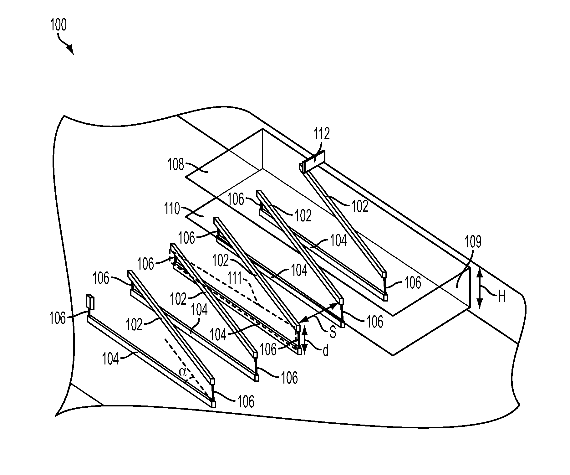
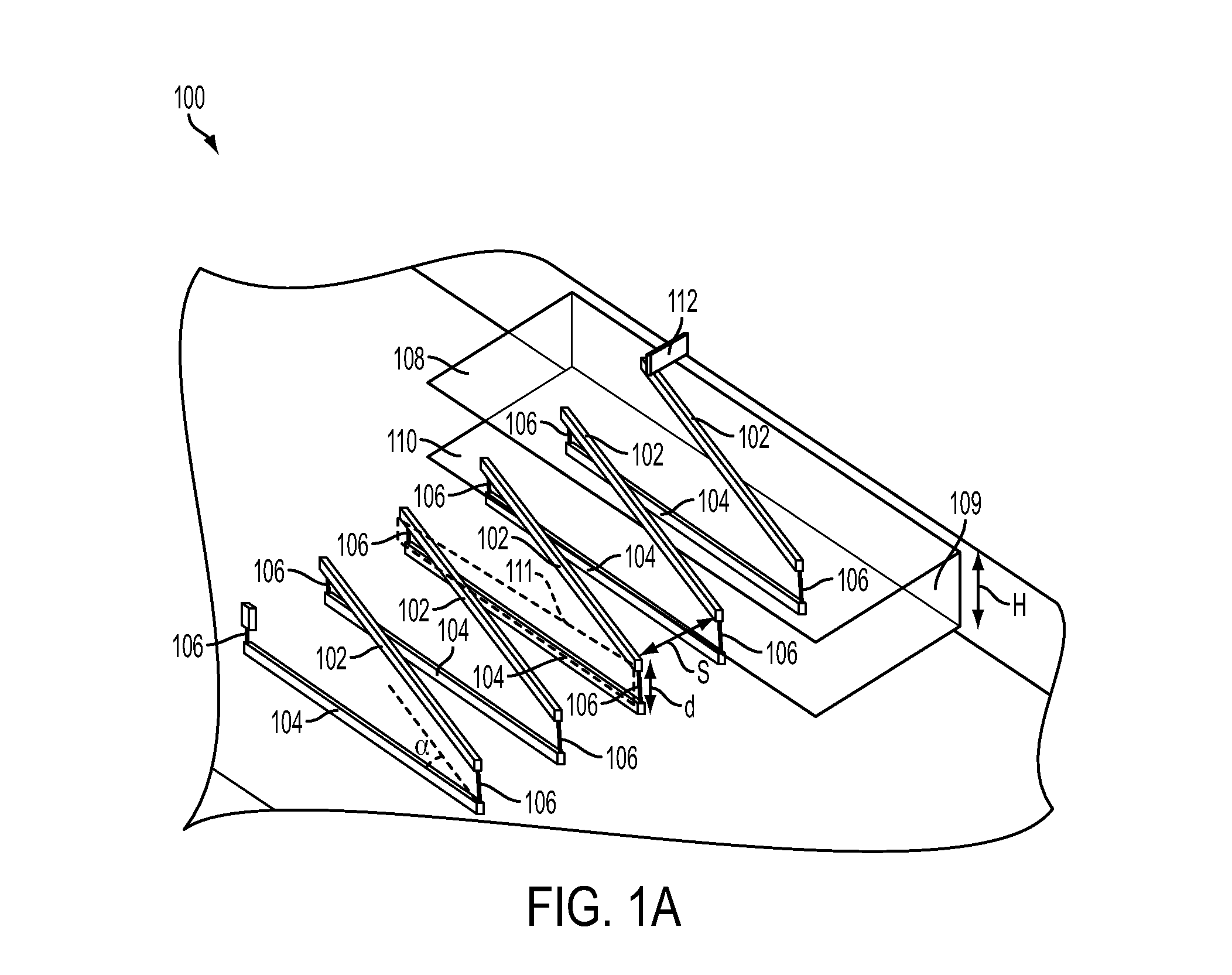
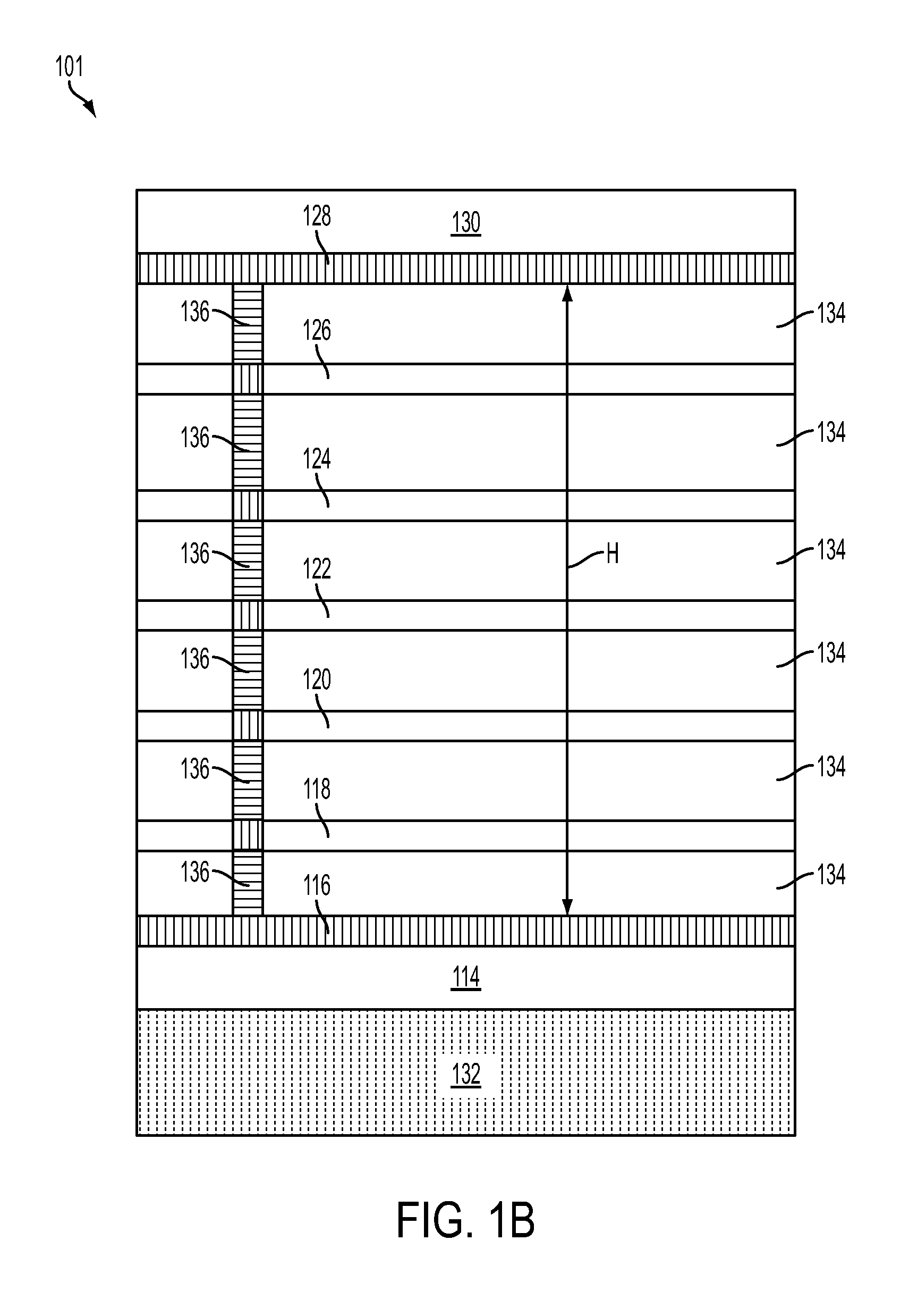
[0011]FIG. 1A is a schematic diagram showing an exemplary on-chip rectangular helix antenna according to some embodiments. FIG. 1B is a schematic diagram showing exemplary layers of an integrated circuit for the on-chip rectangular helix antenna in FIG. 1A, according to some embodiments. In parts of the description below, elements of FIG. 1A and FIG. 1B are referenced together.

[0012]The rectangular helix antenna 100 in an integrated chip includes upper electrodes 102 disposed in a first metal layer, e.g., 126, lower electrodes 104 disposed in a second metal layer, e.g., 118, and side electrodes 106 conn...


PUM


Abstract

A rectangular helix antenna in an integrated circuit includes upper electrodes disposed in a first metal layer, lower electrodes disposed in a second metal layer, and side electrodes connecting the upper electrodes with the lower electrodes, respectively. The upper electrodes are disposed at an angle with respect to the lower electrodes. The upper electrodes, the lower electrodes, and the side electrodes form one continuous electrode spiraling around an inner shape of a rectangular bar. A micro-electromechanical system (MEMS) helix antenna has a similar structure to the rectangular helix antenna, but can have an inner shape of a bar.

Description

TECHNICAL FIELD[0001]The present disclosure relates generally to an antenna and more particularly an on-chip helix antenna.BACKGROUND[0002]For system-on-chip (SOC) applications, on-chip antenna helps integration and keeps the cost down, e.g., for millimeter wave wireless communication, WiFi, and telecommunication, etc. However, for a conventional patch antenna for millimeter wave communication, the performance is an issue with about only 5 dBi gain. Also, the large size of the on-chip patch antenna (e.g., 1.18 mm×0.89 mm for a 77 GHz application) and the antenna cost are problematic. Accordingly, new structures and methods are desired to solve the above problems.BRIEF DESCRIPTION OF THE DRAWINGS[0003]Reference is now made to the following descriptions taken in conjunction with the accompanying drawings, in which:[0004]FIG. 1A is a schematic diagram showing an exemplary on-chip rectangular helix antenna according to some embodiments;[0005]FIG. 1B is a schematic diagram showing exempl...

Claims


Application Information

Patent Timeline
Patent Type & Authority Applications(United States)
IPC IPC(8): H01Q1/36
CPCH01Q1/38H01Q23/00H01Q11/08H01Q1/36B81B7/02H01Q1/362H01Q1/48
Inventor HUNG, CHENG-HSIENLIN, YU-LINGCHEN, HO-HSIANG
Owner TAIWAN SEMICON MFG CO LTD
Learn More