Systems and methods for compressing and/or expanding a gas utilizing a bi-directional piston and hydraulic actuator

a technology of bi-directional pistons and hydraulic actuators, applied in the direction of positive displacement liquid engines, fluid couplings, greenhouse gas reduction, etc., can solve the problems of reducing the ability of power plants to optimally meet fluctuating power demands, inability to completely shut down power plants, and increasing green house gas emissions

Inactive Publication Date: 2012-04-26
GENERAL COMPRESSION
View PDF1 Cites 39 Cited by
  • Summary
  • Abstract
  • Description
  • Claims
  • Application Information

AI Technical Summary

Benefits of technology

[0009]Systems, methods and devices for optimizing bi-directional piston movement within a device or system used to compress and / or expand a gas, such as air, are described herein. In some embodiments, a compressed air device and / or system can include a first pneumatic cylinder, a second pneumatic cylinder, a hydraulic actuator, and a hydraulic controller. The first pneumatic cylinder has a first working piston disposed therein for reciprocating movement in the first pneumatic cylinder and which divides the first pneumatic cylinder into a first pneumatic chamber and a second pneumatic chamber, each fluidically coupleable to a gas source. The hydraulic actuator is coupled to the first working piston. The second pneumatic cylinder has a second working piston disposed therein for reciprocating movement in the second pneumatic cylinder and which divides the second pneumatic cylinder into a third pneumatic chamber and a fourth pneumatic chamber, each fluidically coupleable to a compressed gas storage chamber. The hydraulic controller is fluidically coupleable to the hydraulic actuator and is operable in a compression mode in which gas is discharged from the second pneumatic cylinder to the compressed gas storage chamber at a higher pressure than it enters the first pneumatic cylinder from the gas source, and an expansion mode in which gas is discharged from the first pneumatic cylinder to the gas source at a lower pressure than it enters the second pneumatic cylinder from the compressed gas storage chamber. Operation of the hydraulic controller in the compression mode produces a hydraulic actuator force on the first working piston sufficient to move the first working piston: a) in a first direction such that gas contained in the first pneumatic chamber is discharged from the first pneumatic chamber into the third pneumatic chamber, and b) in a second, opposite, direction such that gas contained in the second pneumatic chamber is discharged from the second pneumatic chamber into the fourth pneumatic chamber.

Problems solved by technology

Electric power plants are also constrained in terms of how quickly they can start-up and shut-down, and it is commonly infeasible to completely shut-down a power plant.
The combination of power output constraints, and start-up and shut-down constraints, restricts a power plant's ability to optimally meet a fluctuating power demand.
These restrictions may lead to increased green house gas emissions, increased overall fuel consumption, and / or to potentially higher operating costs, among other drawbacks.
Existing energy storage technologies, however, have drawbacks.
By way of example, batteries, flywheels, capacitors and fuel cells may provide significant power with relatively fast response times, but have limited energy storage capabilities which limits their utility, and these storage technologies may be costly to implement.
Installations of other larger energy capacity systems, such as pumped hydro systems, require particular geological formations that might not be available at all locations.
Absent suitable energy storage systems, such intermittent power production sites may not be capable of operating at full capacity.
Electric power consumption sites, such as buildings, towns, cities, commercial facilities, military facilities, may have consumption that periodically exceeds electricity transmission capabilities.
Absent suitable energy storage systems, such electric power consumers may not be capable of operating at preferred levels.
Additionally or alternatively, air at pressures higher than 35 atmospheres may need to be throttled prior to expansion in the turbine, incurring energy losses that reduce the efficiency of the system, and / or reduce the energy density that a storage structure may accommodate.
Additionally, to increase electrical energy produced per unit of air expanded through the turbine, compressed air in such systems is often heated and / or pre-heated to elevated temperatures (e.g., 1,000° C.) during and / or prior to expansion by burning fossil fuels, which both increases the cost of energy from the system and produces fuel combustion emissions associated with the storage of energy.
In such a system, the air may still achieve substantial temperatures during each stage of compression prior to being cooled, which introduces inefficiencies in the system.

Method used


Image

  • Systems and methods for compressing and/or expanding a gas utilizing a bi-directional piston and hydraulic actuator
  • Systems and methods for compressing and/or expanding a gas utilizing a bi-directional piston and hydraulic actuator
  • Systems and methods for compressing and/or expanding a gas utilizing a bi-directional piston and hydraulic actuator

Examples


Embodiment Construction

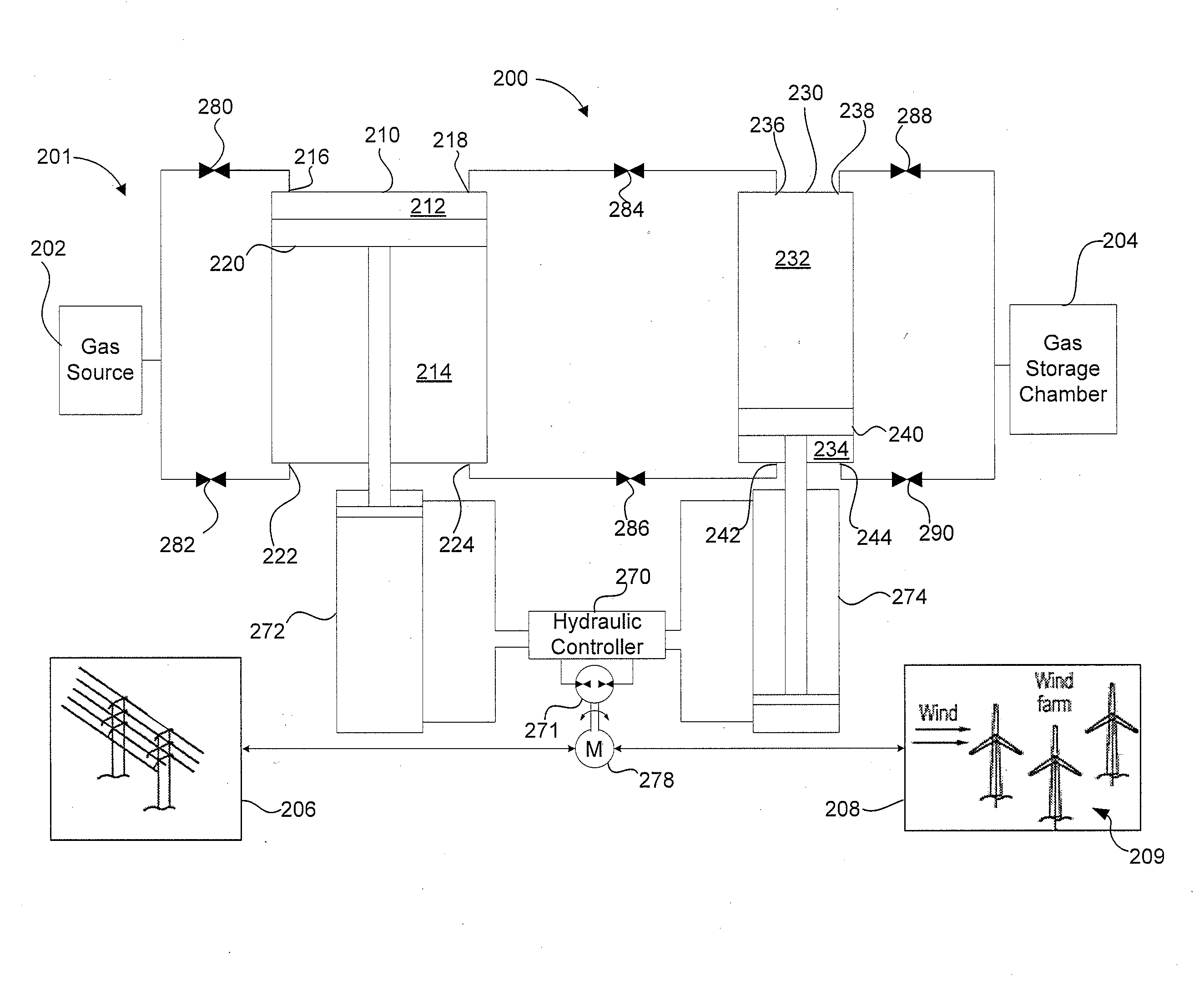
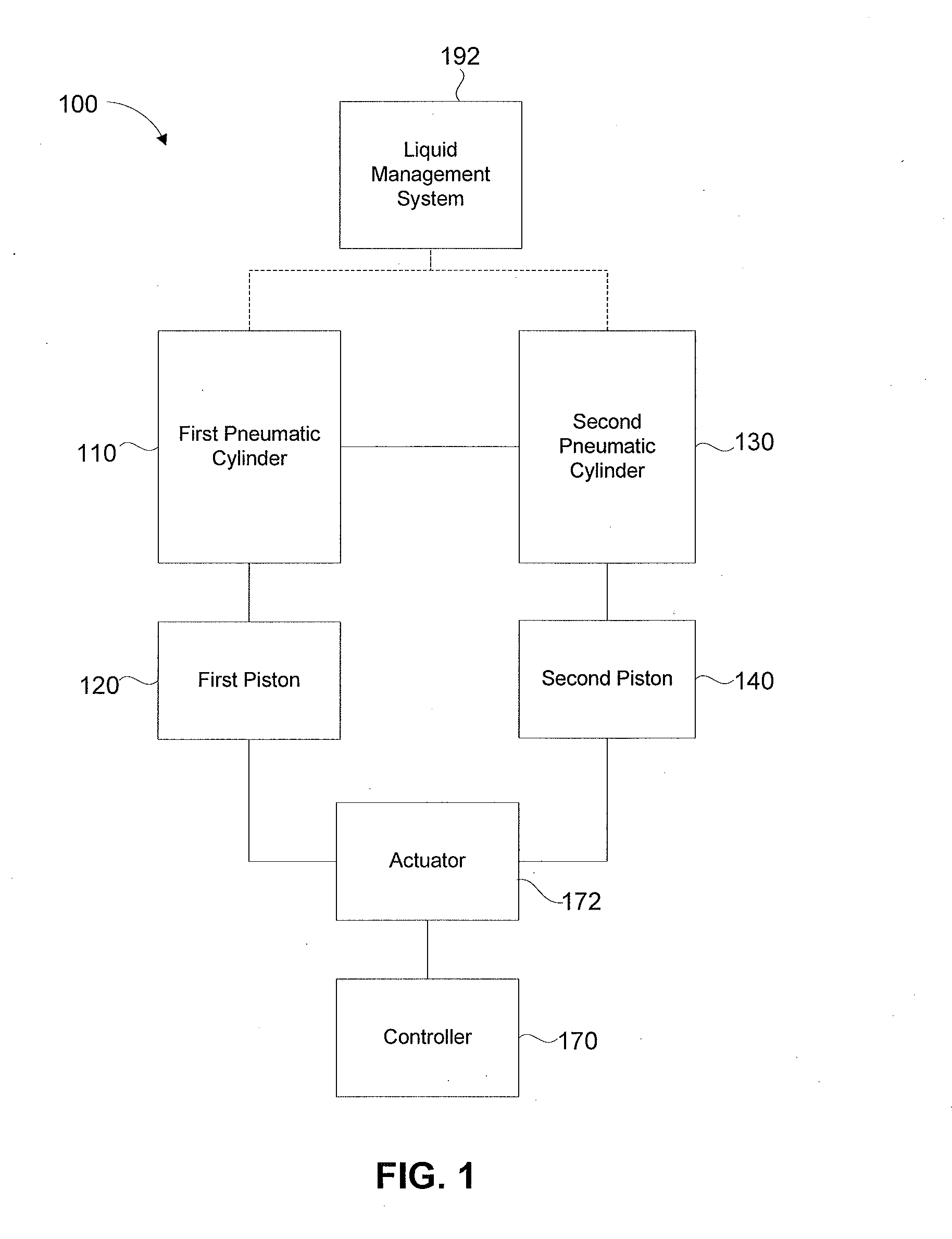
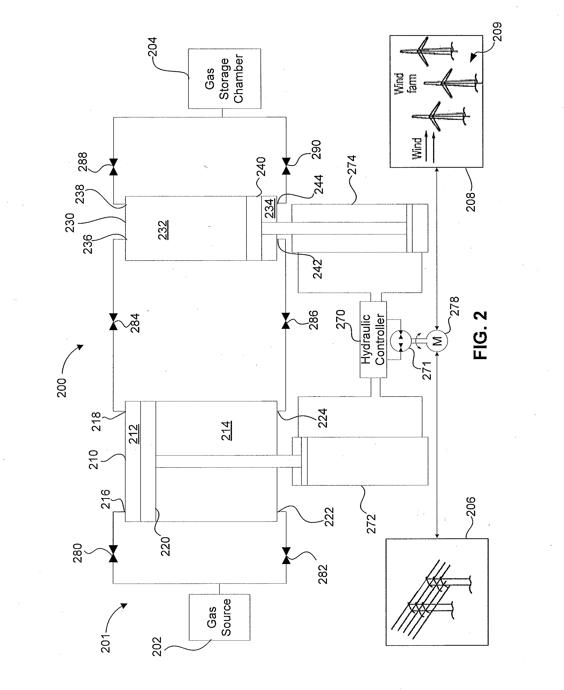
[0017]Systems, devices and methods for optimizing and efficiently operating a gas compression and / or expansion system are disclosed herein. The gas compression and / or expansion systems can include one or more double-acting working pistons movably disposed within a cylinder to compress gas within a working chamber and configured to compress gas when moved in more than one direction. For example, the double-acting piston can be configured to compress gas both when moved in a first direction and when moved in a second direction opposite to the first direction. As used herein the term “piston” is not limited to pistons of circular cross-section, but can include pistons with a cross-section of a triangular, rectangular, multi-sided shape, or conformable shape. The gas compression and / or expansion systems can be configured for two or more stages of gas compression and / or expansion.

[0018]In some embodiments, the double-acting working piston within a gas compression and / or expansion system ...


PUM


Abstract

Systems, methods and devices for optimizing bi-directional piston movement within a device or system used to compress and/or expand a gas, such as air, are described herein. In some embodiments, a compressed air device and/or system can include a first pneumatic cylinder, a second pneumatic cylinder, a hydraulic actuator, and a hydraulic controller. The first pneumatic cylinder has a first working piston disposed therein for reciprocating movement in the first pneumatic cylinder and the hydraulic actuator is coupled to the first working piston. The second pneumatic cylinder has a second working piston disposed therein for reciprocating movement in the second pneumatic cylinder. The hydraulic controller is fluidically coupleable to the hydraulic actuator and is operable in a compression mode.

Description

BACKGROUND[0001]The invention relates generally to systems, devices and methods for the compression and / or expansion of a gas, such as air, and particularly to a system, device and method for optimizing the energy efficiency and power density of a compressed air energy storage system.[0002]Traditionally, electric power plants have been sized to accommodate peak power demand. Moreover, electric power plant sizing must take into account their maximum power output, minimum power output, and a middle power output range within which they most efficiently convert fuel into electricity. Electric power plants are also constrained in terms of how quickly they can start-up and shut-down, and it is commonly infeasible to completely shut-down a power plant. The combination of power output constraints, and start-up and shut-down constraints, restricts a power plant's ability to optimally meet a fluctuating power demand. These restrictions may lead to increased green house gas emissions, increase...

Claims


Application Information

Patent Timeline
Patent Type & Authority Applications(United States)
IPC IPC(8): F15B1/027
CPCF03D9/028F04B41/02Y02E60/15Y02E10/72F04B41/06F03D9/17F03D9/28F03D9/257Y02E60/16Y02E70/30
Inventor INGERSOLL, ERIC D.ABORN, JUSTIN A.BLIESKE, MATTHEW
Owner GENERAL COMPRESSION
Why Eureka
Try Eureka