Aircraft fuel tank ventilation

a technology for aircraft and fuel tanks, applied in the direction of defrosting, domestic cooling devices, applications, etc., can solve the problems of affecting the reliability of fuel system components, so as to reduce maintenance activities, improve fuel system components reliability, and reduce microbiological contamination

Active Publication Date: 2012-04-26
AIRBUS OPERATIONS LTD
View PDF2 Cites 10 Cited by
  • Summary
  • Abstract
  • Description
  • Claims
  • Application Information

AI Technical Summary

Benefits of technology

[0010]The invention is advantageous in that water can be effectively removed from air entering the aircraft fuel tank. In this way, the content of water in the fuel tank can be kept low, which improves fuel system component reliability, reduces maintenance activities, and reduces microbiological contamination.
[0012]The cold plate may have a plurality of ribs on its surface. As water condenses out of the air flow on the surface of the cold plate through nucleation and growth it beads in grooves between the ribs. The cold plate may be arranged substantially vertically with the ribs inclined with respect to the direction of the air flow. The combined effect of gravity and the air flow encourages the water beads to flow towards the bottom of the plate. To increase the efficiency of the refrigerative dehumidifying device, the cold plate may be one of an array of similar cold plates. These may be arranged side by side to allow the air flow to pass between adjacent plates.
[0013]Water from the refrigerative dehumidifying device may be collected in a sump. In a preferred embodiment, the sump is disposed beneath an array of vertically arranged cold plates. The location and shape of the sump can be tailored according to the refrigerating element(s) used. The sump will need to be drained and this may be done periodically, e.g. during maintenance activities, but is preferably done continuously whilst the device is operating. For example, a discharge tube may be used to pass condensate from the refrigerating element to the atmosphere. The discharge tube may be connected at one end to the sump. At its other end, motion of the aircraft may be used to generate suction within the discharge tube drawing the water out into the atmosphere. This is preferable as no active pumping is required, which reduces power consumption and parts. However, a pump may be used if desired.

Problems solved by technology

Water is an unavoidable contaminant in fuel.
It can affect fuel system component reliability and lead to operational delays and increased maintenance activities.
This results in a net outflow of air through the ventilation system.
This results in a net inflow of ambient air through the ventilation system.

Method used


Image

  • Aircraft fuel tank ventilation
  • Aircraft fuel tank ventilation
  • Aircraft fuel tank ventilation

Examples


Embodiment Construction

)

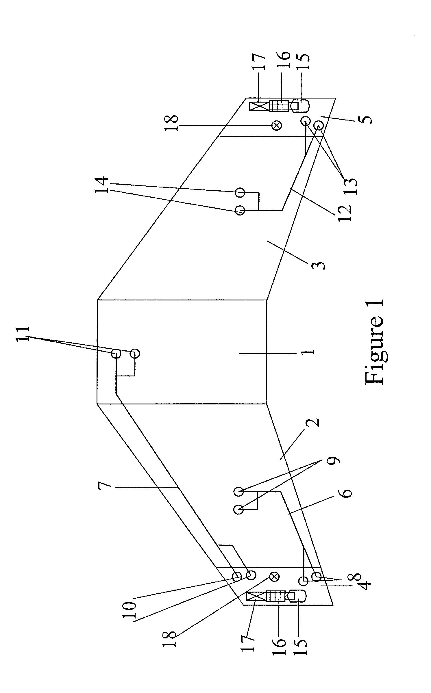
[0023]FIG. 1 shows a general ventilation system architecture for a three-tank configuration of an aircraft fuel system. The fuel system includes a centre tank 1, a left wing tank 2 and a right wing tank 3. The ventilation system includes a left vent tank 4 and a right vent tank 5. The left vent tank 4 ventilates the centre tank 1 and the left wing tank 2 by means of ventilation pipes 6, 7 which open into ventilation inlets 8, 9, 10, 11. The right vent tank 5 ventilates the right wing tank 3 by means of ventilation pipe 12 which opens into ventilation inlets 13 and 14.

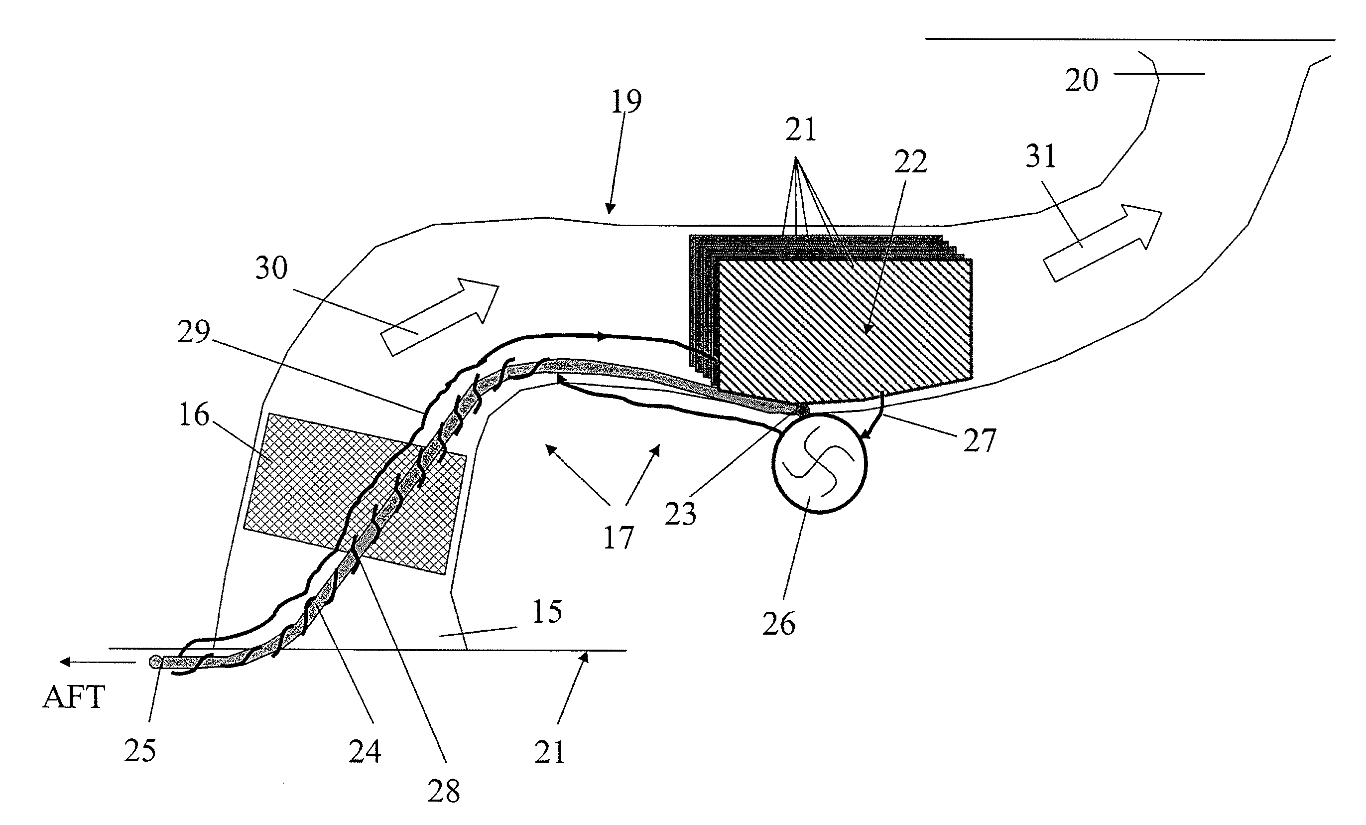
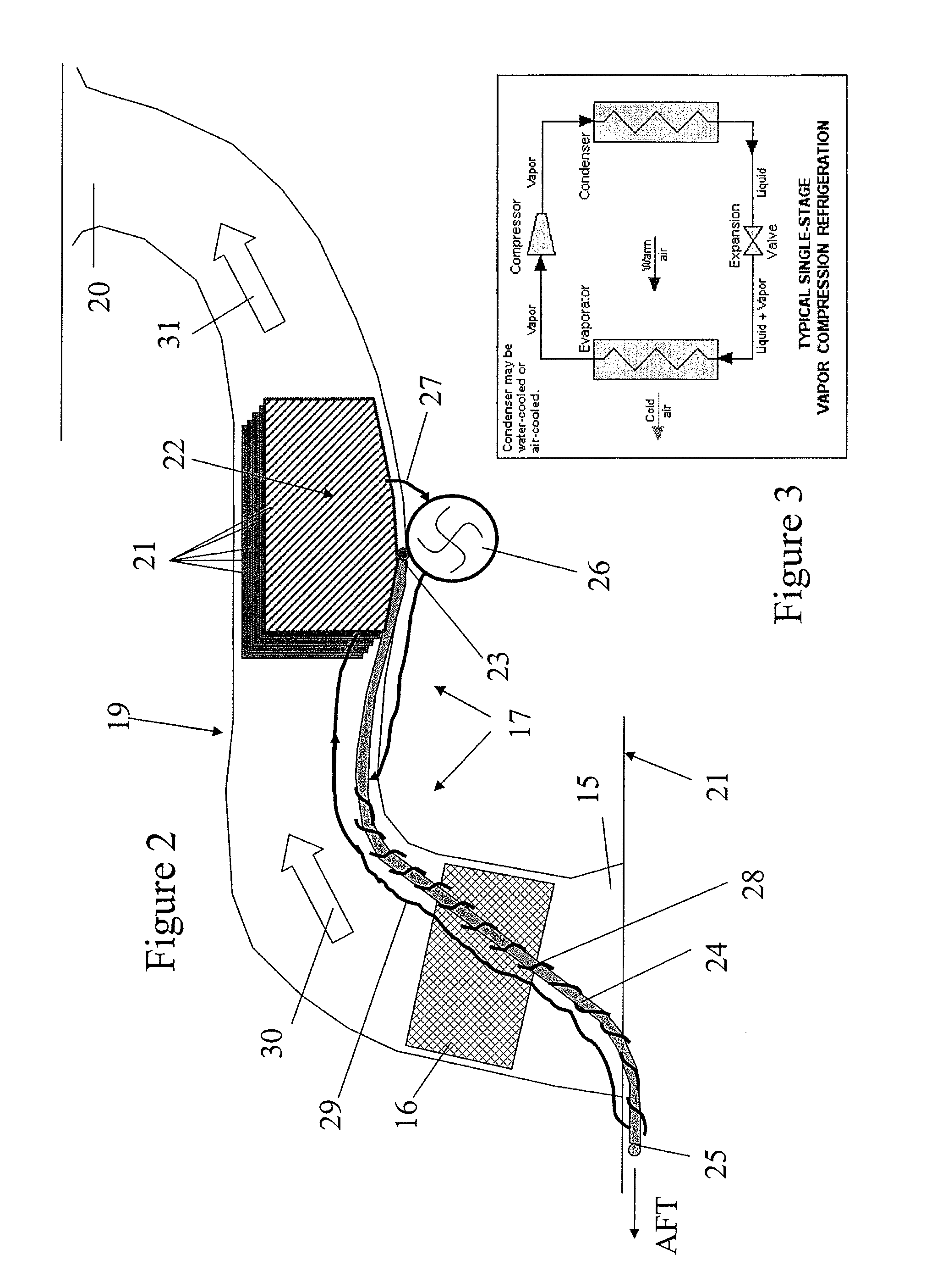
[0024]Each vent tank 4, 5 includes a NACA duct assembly including a NACA vent, or NACA scoop, 15 which opens to the atmosphere on the lower aerodynamic surface of the aircraft wing. The vent tanks 4, 5 further include a vent protector, or flame arrestor, 16 and a dehumidifying device 17. The dehumidifying device 17 is disposed in flow communication between the NACA vent 15 and the respective vent tank 4, 5. The vent ta...


PUM


Abstract

An aircraft fuel tank ventilation system, comprising a refrigerative dehumidifying device having a refrigerating element in contact with air flowing between a vent open to the atmosphere and a fuel tank. Also, a method of dehumidifying air introduced into an aircraft fuel tank via the ventilation system, the method comprising directing atmospheric air from the vent into contact with the refrigerating element, and cooling the refrigerating element so as to remove water vapour from the air flowing from the vent towards the fuel tank by condensation. An aircraft fuel tank ventilation system, comprising a refrigerative dehumidifying device having a refrigerating element in contact with air flowing between a vent open to the atmosphere and a fuel tank. Also, a method of dehumidifying air introduced into an aircraft fuel tank via the ventilation system, the method comprising directing atmospheric air from the vent into contact with the refrigerating element, and cooling the refrigerating element so as to remove water vapour from the air flowing from the vent towards the fuel tank by condensation.

Description

FIELD OF THE INVENTION[0001]The present invention relates to an aircraft fuel tank ventilation system having a refrigerative dehumidifying device. The present invention also relates to a method of dehumidifying air introduced into an aircraft fuel tank via the ventilation system using the refrigerative dehumidifying device.BACKGROUND OF THE INVENTION[0002]Water is an unavoidable contaminant in fuel. It can affect fuel system component reliability and lead to operational delays and increased maintenance activities. In addition, the propensity for microbiological contamination is directly proportional to the presence of water and the temperature within fuel tanks. Sources of water in aircraft fuel tanks is from fuel loaded into the aircraft fuel tanks during refuel (dissolved water) and from air entering the aircraft fuel tanks via its ventilation system. It is estimated that up to 30-40% of water in the fuel of aircraft fuel tanks is currently entering via the ventilation system, dep...

Claims


Application Information

Patent Timeline
Patent Type & Authority Applications(United States)
IPC IPC(8): B64D37/32B64D37/06B64D37/34F16K24/00F25D21/14
CPCB64D37/32Y10T137/86324
Inventor LAM, JOSEPH K-WTICHBORNE, FRANKLINMASTERS, SIMONPARMENTER, DAVID
Owner AIRBUS OPERATIONS LTD
Why Eureka
Try Eureka