Composite drill pipe and method for forming same

a technology of composite drill pipe and metal composite, which is applied in the direction of hose connection, screw threaded joint, borehole/well accessories, etc., can solve the problems of long time-consuming and laborious, inefficient ability to adjust the drilling rate, reach and direction in the pursuit of oil traps, and difficulty in adjusting or performing short radius turns, etc., to achieve enhanced stress load diffusion, enhanced load diffusion across the metal-composite interface, and enhanced stress load diffusion

Active Publication Date: 2012-04-26
ADVANCED COMPOSITE PRODS & TECH
View PDF3 Cites 7 Cited by
  • Summary
  • Abstract
  • Description
  • Claims
  • Application Information

AI Technical Summary

Benefits of technology

[0025]In a third example of the present invention, load diffusion across the metal-composite interface is further enhanced by utilizing an alternate construction. The cross-sectional area of the metal-composite interface is altered by positioning the ends of the linearly tapered cylindrical metal end fittings and sleeves longitudinally offset from one another. In one formation of the resulting nesting cavity, the cylindrical wall of the end fitting extends deeper into the pipe segment interior than the concentrically surrounding sleeve wall. Thus, a reinforced and nested metal-composite interface is maintained while providing enhanced diffusion of stress loads across the joint surfaces and in turn, providing a supported degree of flexing at the juncture.

Problems solved by technology

Oil well drilling is often performed from drilling platforms, which, for deep water applications may involve costs of several hundred thousand dollars per day.
The ability to adjust drilling rate, reach and direction in the pursuit of oil traps has long been rendered inefficient by the lack of a reliable and durable pipe string and method for obtaining feedback during drilling.
The stiffness associated with steel has also made adjusting to or performing short radius turns difficult and dangerous as drill operators are essentially guessing at the changes in subterraneous conditions as the pipe progresses without consistent signal feedback.
The drilling entrepreneur, therefore, has been limited for some time by the stiffness, the unit weight, and the fatigue, shear and tensile strength limits of metal pipe.
The dilemma thus far has been in successfully leading a signal down the pipe.
Signals that are traditionally carried down through the pipe tend to suffer adverse consequences of the rigorous and treacherous environment associated with drilling.
Composites, while sufficiently lightweight and durable for deep and directional drilling, are less effective at forming the mechanical joints required in drill pipes.
This synergistic aspect of composite pipe has not been fully recognized nor exploited in the art simply because the technical challenge of forming an effective connection between the composite tube wall and the end fitting has overwhelmed all other considerations.
At the core is the inherent difficulty in forming a high integrity interface between the composite pipe wall and the adjoining surfaces of the end fitting.
While suitable for the purposes intended each of the foregoing assemblies include threaded or otherwise releasably engaged parts clamping the composite between each other with inherently uneven load concentrations resulting in highly uneven shear stresses.
This uneven load distribution between adjacent parts, of course, results in correspondingly uneven local strain deformations when exposed to the various high loadings in the course of use.
There is therefore an inherent incidence of local bond separation between the composite itself and the adjoining fitting surface, with some consequence for failure.
Once again, while a change is realized from these radial interconnections the essentially separated nature of a single metal to composite surface interface is also susceptible to uneven load transfer with the consequent local separations an inherent possibility.
Tew appears to propose an outer protective sheath lacking a tapered surface interface and suffers the shortcoming that, particular to long reach applications, the coupling itself fails to provide a high strength joint capable of carrying the high torsional force necessary to withstand the loads of both extended reach applications and short radius.
Moreover, such assemblies suffer from a lack of another significant attribute, namely the bridging of a protected electrical signal between pipe connections.
Additionally, where electrical leads are incorporated throughout the pipe string, the signal and power carrying arrangements suffer from being lead down the string either within the pipe hollow passage or external the pipe exposed to damaging objects.
Thus while suitable for the purposes intended these prior art teachings do not avail themselves to all the advantages of a composite, non-conducting pipe string and the protective capabilities of embedding a conductor in the composite walls and it is these advantages that are realized herein.
Such arrangements are either prone to damage or add significant weight and contribute to inflexibility in the pipe string by incorporating full length metal tubes within the structure.
The adductive loop coupling has not proven particularly acceptable and the electrical cable exposed on the interior of a pipe subjects the cable to the elements within the pipe and to damage from components extended through the pipe.
Furthermore, such pipe devices do not lend themselves to short turn pipe constructions.

Method used


Image

  • Composite drill pipe and method for forming same
  • Composite drill pipe and method for forming same
  • Composite drill pipe and method for forming same

Examples


Embodiment Construction

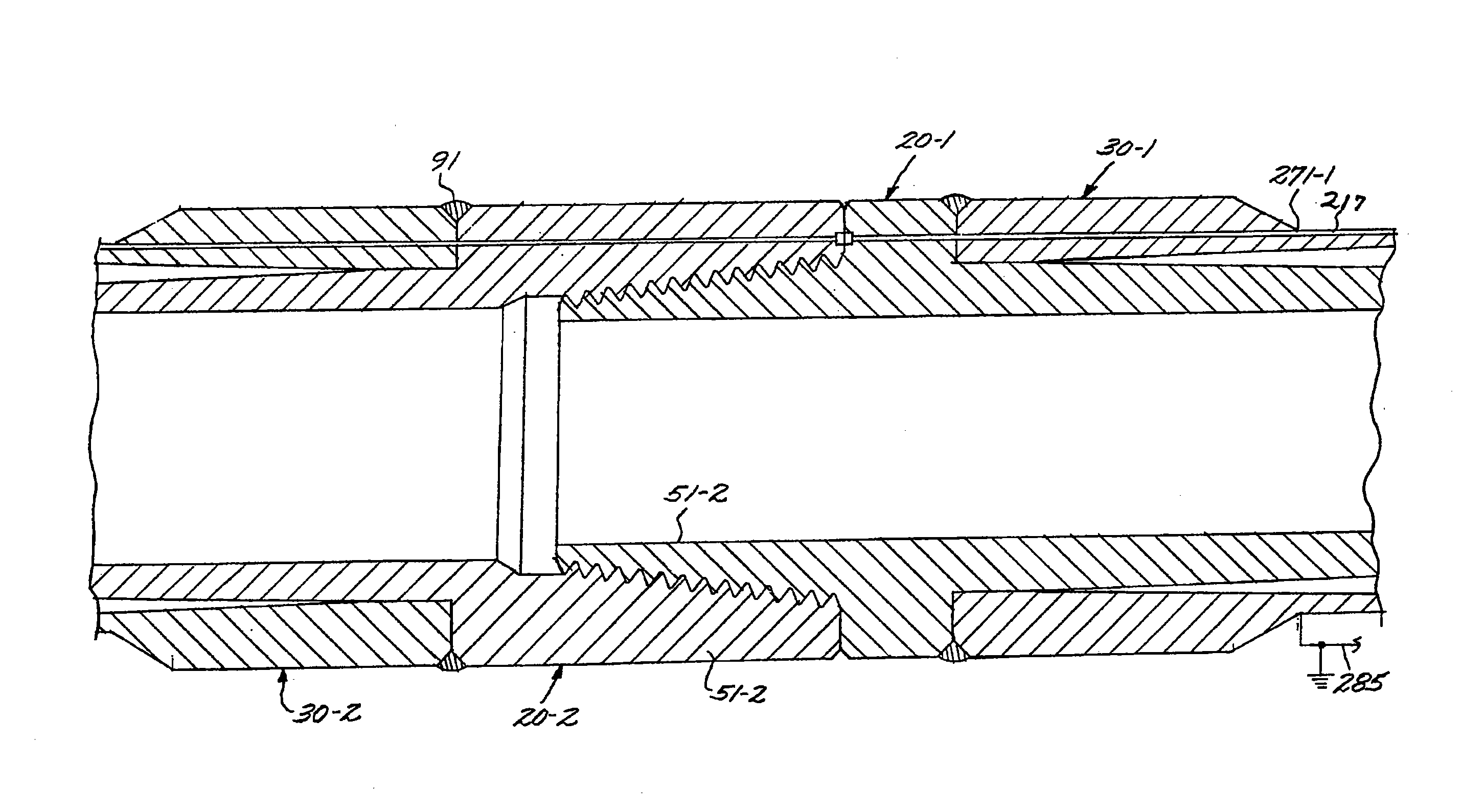
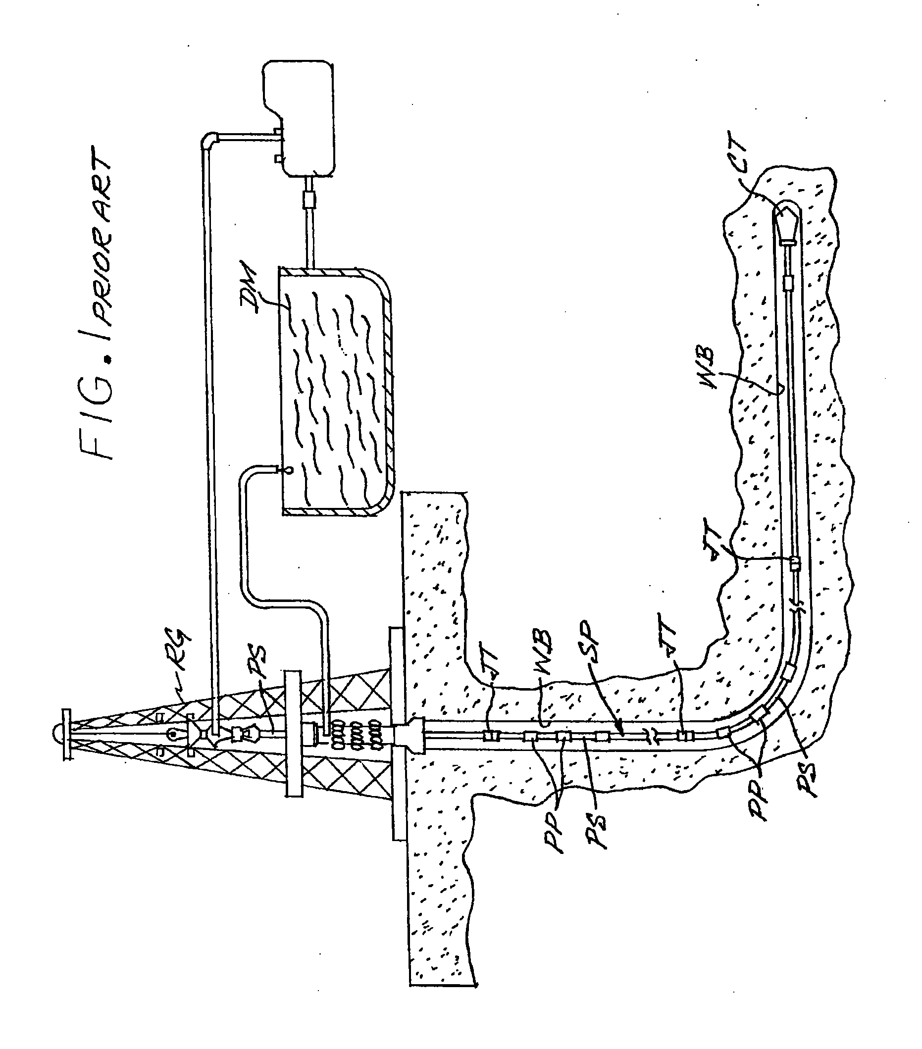
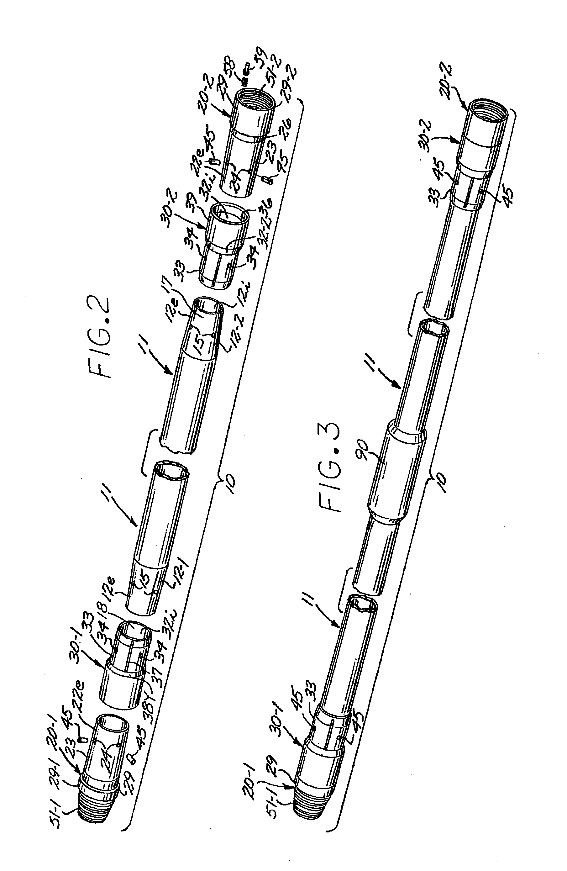
[0045]As shown in FIG. 1 current drilling practices depend on a string SP composed of drill pipe segments PS connected end-to-end to turn a cutting tool CT mounted on the lower string end. In the course of such turning, the tool CT grinds and penetrates through the bottom of the well bore WB with the particulates continuously brought out to the surface by a circulating flow of drilling mud DM pumped into the bore to equalize bore pressures. As readily available formations are depleted these drilling projects now extend to much greater depth, and / or greater lateral reach, with the weight of the pipe string SP and / or its friction load in the well bore setting the practical exploration limits. The complexity of a drilling rig RG conformed for such long reach drilling is enormous and the logistics of its movement alone, encourage directional capability along with an increasing pipe string. This same complexity of the rig also determines the manipulation convenience of each of the pipe s...


PUM

PropertyMeasurementUnit
lengthaaaaaaaaaa
outer diameteraaaaaaaaaa

Abstract

A lightweight and durable drill pipe string capable of short radius drilling formed using a composite pipe segment formed to include tapered wall thickness ends that are each defined by opposed frustoconical surfaces conformed for self-aligning receipt and intimate bonding contact within an annular space between corresponding surfaces of a coaxially nested set of metal end pieces and a set of nonconductive sleeves. The distal peripheries of the nested end pieces and sleeves are then welded to each other and the sandwiched and bonded portions are radially pinned. The composite segment may include imbedded conductive leads and the axial end portions of the end pieces are shaped to form a threaded joint with the next pipe assembly that includes contact rings in the opposed surfaces of the pipe joint for contact together.

Description

CROSS-REFERENCES TO RELATED APPLICATIONS[0001]The teachings herein constitute a divisional application Ser. No. 12 / 323,067 filed Nov. 25, 2008 which was continuation-in-part of the matter disclosed in U.S. patent application Ser. No. 10 / 952,135 filed Sep. 28, 2004, now U.S. Pat. No. 7,458,617, and the benefit of this earlier filing data is claimed for all matter common therewith.STATEMENT OF GOVERNMENT INTEREST[0002]This invention was partly funded by the Government of the United States of America under Cooperative Agreement No. DE-FC26-99FT40262 awarded by the U.S. Department of Energy and the Government of the United States of America has certain rights in the invention.BACKGROUND OF THE INVENTION[0003]1. Field of the Invention[0004]The present invention relates to drill pipe strings and the method for forming the same, and more particularly to providing a lightweight string for extended reach and short radius drilling and to protecting connections for transmitting signal and / or p...

Claims


Application Information

Patent Timeline
Patent Type & Authority Applications(United States)
IPC IPC(8): F16L17/00
CPCE21B17/003E21B17/028F16L13/103F16L15/08Y10T29/49826E21B17/206E21B17/0285F16L25/0018E21B17/20F16L31/00
Inventor LESLIE, JAMES C.LESLIE, II, JAMES C.HEARD, JAMESTRUONG, LIEMJOSEPHSON, MARVIN
Owner ADVANCED COMPOSITE PRODS & TECH
Why Eureka
Try Eureka