Light Extraction Films for Increasing Pixelated OLED Output with Reduced Blur

Active Publication Date: 2012-04-26
3M INNOVATIVE PROPERTIES CO
View PDF30 Cites 79 Cited by
  • Summary
  • Abstract
  • Description
  • Claims
  • Application Information

AI Technical Summary

Benefits of technology

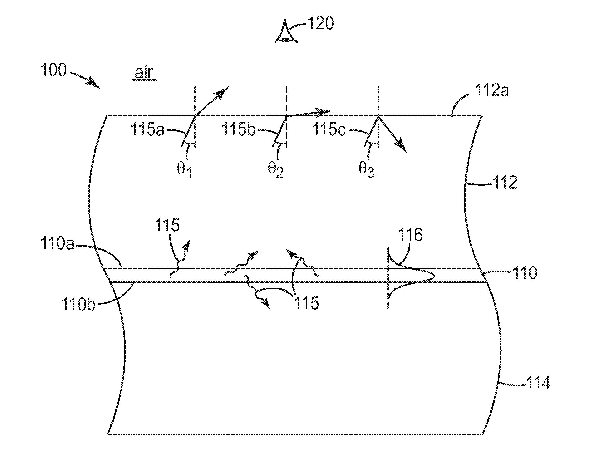
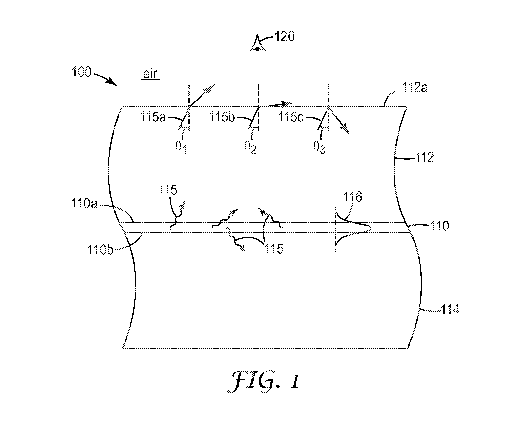
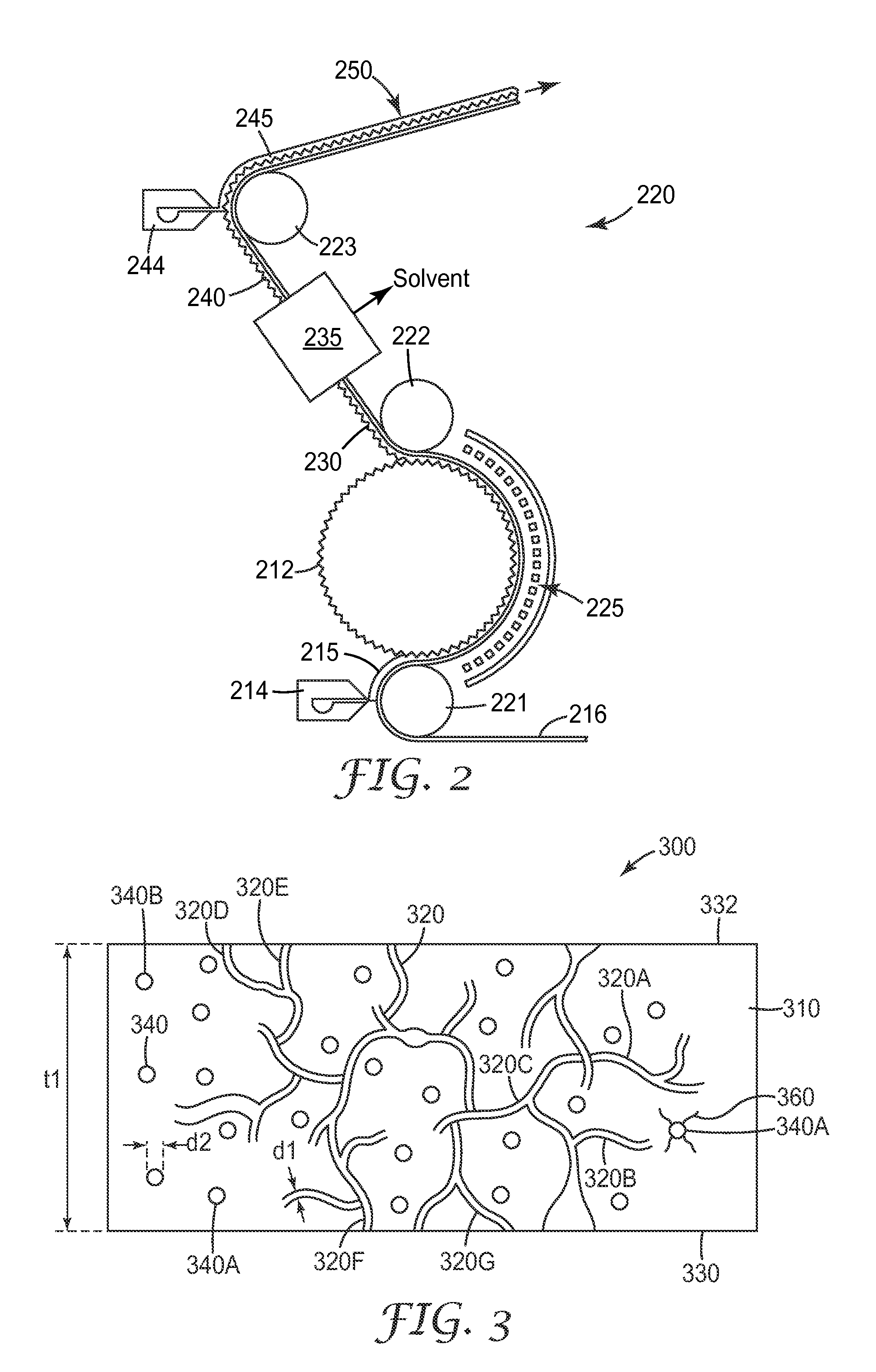
[0005]We have developed a new family of optical films that can be used in combination with OLEDs and other self-emissive light sources to extract light from such d

Problems solved by technology

One issue of concern to some OLED manufacturers and designers is the less-than-ideal efficiencies exhibited by OLEDs due to peculiarities of their design.
A number of groups have demonstrated that OLED external efficiency is significantly limited by optical losses within the active emitting layers of the OLED stack itself (due to waveguiding modes within high refractive index organic layers and indium tin oxide), within intermediate-refractive index substrates, and finally due to exciton quenching at the cathode (anode)

Method used


Image

  • Light Extraction Films for Increasing Pixelated OLED Output with Reduced Blur
  • Light Extraction Films for Increasing Pixelated OLED Output with Reduced Blur
  • Light Extraction Films for Increasing Pixelated OLED Output with Reduced Blur

Examples


example 1

50 / 60 Bullet-Shaped Extractors, Adhesive Backfill, No Haze in ULI

[0114]A computer simulation was performed of an OLED with an embedded extraction layer using ray tracing methods and the modeling package LIGHTTOOLS (commercially available from Optical Research Associates, Pasadena, Calif.). The configuration that was simulated is shown generally as OLED device 520 in FIG. 5. The microreplicated nanovoided material of Ultra Low Index (ULI) (see e.g. layer 414 in FIG. 5) was modeled as having a refractive index of 1.2 and zero haze. The refractive index of the carrier film or substrate (see e.g. layer 412 in FIG. 5) was selected to be 1.65 to model a polyethylene terephthalate (PET) substrate. The refractive index of the backfill layer (see e.g. layer 416 of FIG. 5) was selected to be 1.48 to model Soken 2032 pressure sensitive adhesive (commercially available from Soken Chemical & Engineering Co., Ltd, Japan). The substrate was assumed to have a thickness of 100 μm.

[0115]The extractio...

example 2

50 / 60 Bullet-Shaped Extractors, Adhesive Backfill, Haze in ULI

[0117]An OLED with an optical extraction film was simulated in the same way as in Example 1, except that some haze was included in the nanovoided Ultra Low Index (ULI) layer. This was simulated by adding scattering centers to the simulated nanovoided layer, where the scattering centers scattered light primarily in the forward 45° cone angle, and with a scattering probability set at 20% (i.e., the probability for a light ray to be scattered at least once upon traveling through the layer was set to 20%). With this built-in haze in the nanovoided layer of the simulated extraction film, the angular color non-uniformity was reduced to 0.010, and the integral gain was improved to 1.51.

example 3

50 / 60 Bullet-Shaped Extractors, HRI Backfill, No Haze in ULI

[0118]An OLED with an optical extraction film was simulated in the same way as in Example 1, except that the refractive index of the nanovoided ULI material was set to 1.26 (rather than 1.2), and the refractive index of the backfill material (see e.g. layer 416 in FIG. 5) was chosen to be 1.65 (rather than 1.48) which is representative of a high refractive index curable resin such as a nanozirconia-filled UV curable acrylate resin, such as those described in U.S. Pat. No. 7,547,476 (Jones et al.).

[0119]The color non-uniformity and integral gain were determined as in Example 1. The calculated color deviation is given in Table 2. The maximum angular color non-uniformity with and without the optical extraction film was 0.0083 and 0.0242, respectively. The integral gain with the extraction film was 1.55.

TABLE 2Δu′v′AngleOLED withΔu′v′(degrees)Extraction FilmOriginal OLED88.50.00220.024285.50.00300.021982.50.00530.020279.50.0083...


PUM

PropertyMeasurementUnit
Lengthaaaaaaaaaa
Thicknessaaaaaaaaaa
Thicknessaaaaaaaaaa

Abstract

Optical films for enhancing light extraction from self-emissive pixelated OLEDs, without introducing significant pixel blur, are disclosed. The extraction films include a flexible carrier film, and a first and second layer carried by the carrier film. The first layer has a nanovoided morphology, includes a polymer binder, and may have a refractive index less than 1.35 or 1.3. An embedded structured surface of light extraction elements is formed between the first and second layers. The extraction film includes a major coupling surface for attachment to an outer surface of the light source. The film is configured such that a land portion between the structured surface and the major coupling surface is thinner than a specified amount, e.g., less than 50, 25, or 10 microns, or less than a thickness of the carrier film.

Description

FIELD OF THE INVENTION[0001]This invention relates generally to optical films having structured surfaces tailored to couple light out of solid state self-emissive lighting devices to increase the brightness thereof, with particular application to self-emissive lighting devices known as organic light emitting devices (OLEDs) (sometimes also referred to as organic light emitting diodes). The invention also pertains to related articles, systems, and methods.BACKGROUND[0002]A wide variety of OLEDs are known. Some OLEDs, referred to as “bottom emitting” OLEDS, emit light through a transparent substrate on which the OLED is fabricated. Others, referred to as “top emitting” OLEDs, emit light in the opposite direction, i.e., away from the substrate on which the OLED is fabricated. Some OLEDs are patterned to form an array of individually addressable OLED emitters, referred to individually as pixels (picture elements) or subpixels (one of several neighboring emitters of different colors that...

Claims


Application Information

Patent Timeline
IPC IPC(8): F21V11/00
CPCB29C35/02B29C35/0866B29C59/046B29C2035/0822H01L51/5275B29C2035/0833B29C2035/0838B29C2035/0877B29C2035/0827H10K50/858
Inventor THOMPSON, DAVID S.
Owner 3M INNOVATIVE PROPERTIES CO
Why Eureka
Try Eureka