Respiration impedance measuring device and respiration impedance display method

a technology of impedance measurement and impedance display, which is applied in the field of respiration impedance measurement, can solve the problems of insufficient removal of noise, and achieve the effects of high precision, high impedance, and high precision

Active Publication Date: 2012-04-26
CHEST CORP +1
View PDF5 Cites 7 Cited by
  • Summary
  • Abstract
  • Description
  • Claims
  • Application Information

AI Technical Summary

Benefits of technology

[0018]According to the present invention: an air vibration pressure by an oscillation wave that is frequency-culled is applied to the inside of an oral cavity; the pressure of the inside of the oral cavity is detected; the flow of breathing is detected; a spectrum is obtained by Fourier-transforming these signals detected; a breathing high frequency component that contributes as a noise is obtained using a spectrum that corresponds to a frequency component culled from the result of the Fourier transformation; the breathing high frequency component is subtracted from a spectrum that corresponds to the frequency component left by the culling; thereby, an oscillation wave component is extracted; computing is executed of dividing a pressure component by a flow component for each of frequencies for the result of this extraction; and, thereby, breathing impedance is obtained. Therefore, the breathing impedance may be obtained using the oscillation wave component from which the breathing high frequency component is securely removed. In addition, a pulse signal is adopted for generating the air vibration pressure by the oscillation wave in pulse drive such that pulses are made positive and negative separately in correspondence to the time of exhalation and the time of inhalation. Breathing resistance, therefore, may be measured under the same physiological condition in periods of exhalation and in periods of inhalation, so that breathing impedance measurement with extremely high precision is enabled through proper measurement.
[0019]According to the present invention: the air vibration pressure by the oscillation wave having only the n / T1 (n: an integer, T1: a real number) frequency components is caused to be generated by supplying the pulse having the cycle T1; therefore, the breathing high frequency component is obtained using the spectrum that corresponds to the frequency component culled; and the breathing high frequency component is subtracted from the spectrum that corresponds to the frequency component left by the culling (frequency component other than the n / T1 frequency component). Therefore, the breathing high frequency component is securely removed to enable the breathing impedance measurement with extremely high precision.
[0020]According to the present invention, a plurality of sine waves at a plurality of different frequencies are combined and, thereby, the air vibration pressure by the oscillation wave that is frequency-component-culled is caused to be generated. As a result, only the breathing high frequency component is included in the spectrum that corresponds to the frequency component culled. Therefore, a breathing high frequency component included in an oscillation signal may be estimated from this breathing high frequency component signal. Hence the breathing high frequency component may securely be removed using this estimated signal to enable the breathing impedance measurement with extremely high precision.
[0021]According to the present invention, an input signal is supplied to a pressurizing executing portion such that the oscillation wave having a desired pressure waveform is the output signal based on the reverse computation using the input signal and the output signal for the pressurizing and a transfer function of the pressurizing executing portion. Therefore, the measurement may be executed using the oscillation wave having the desired pressure waveform and respiratory impedance measurement with extremely high precision is enabled.
[0022]According to the present invention, the input signal is the signal obtained by adding a specific value to each of the frequency components of the signal obtained by the reverse computing, or by reverse computing the signal formed by adding an impulse to the onset portion of the output signal. Therefore, the signal waveform of the result of the reverse computing may be stabilized and, thereby, the measurement using the oscillation wave having a desired waveform may be executed and the respiratory impedance measurement with extremely high precision is enabled.
[0023]According to the present invention, signal processing is executed in a signal processing section T2 (T2=mT1 (m denotes an integer of 1 or larger)). As a result, the spectrum that corresponds to the frequency component left by the culling and the spectrum that corresponds to the frequency component culled are obtained properly to be able to execute a necessary process.

Problems solved by technology

However, the removal of the noises is not sufficient even by the conventional apparatus and realization of a higher-performance respiratory impedance measuring apparatus is demanded.

Method used


Image

  • Respiration impedance measuring device and respiration impedance display method
  • Respiration impedance measuring device and respiration impedance display method
  • Respiration impedance measuring device and respiration impedance display method

Examples


Embodiment Construction

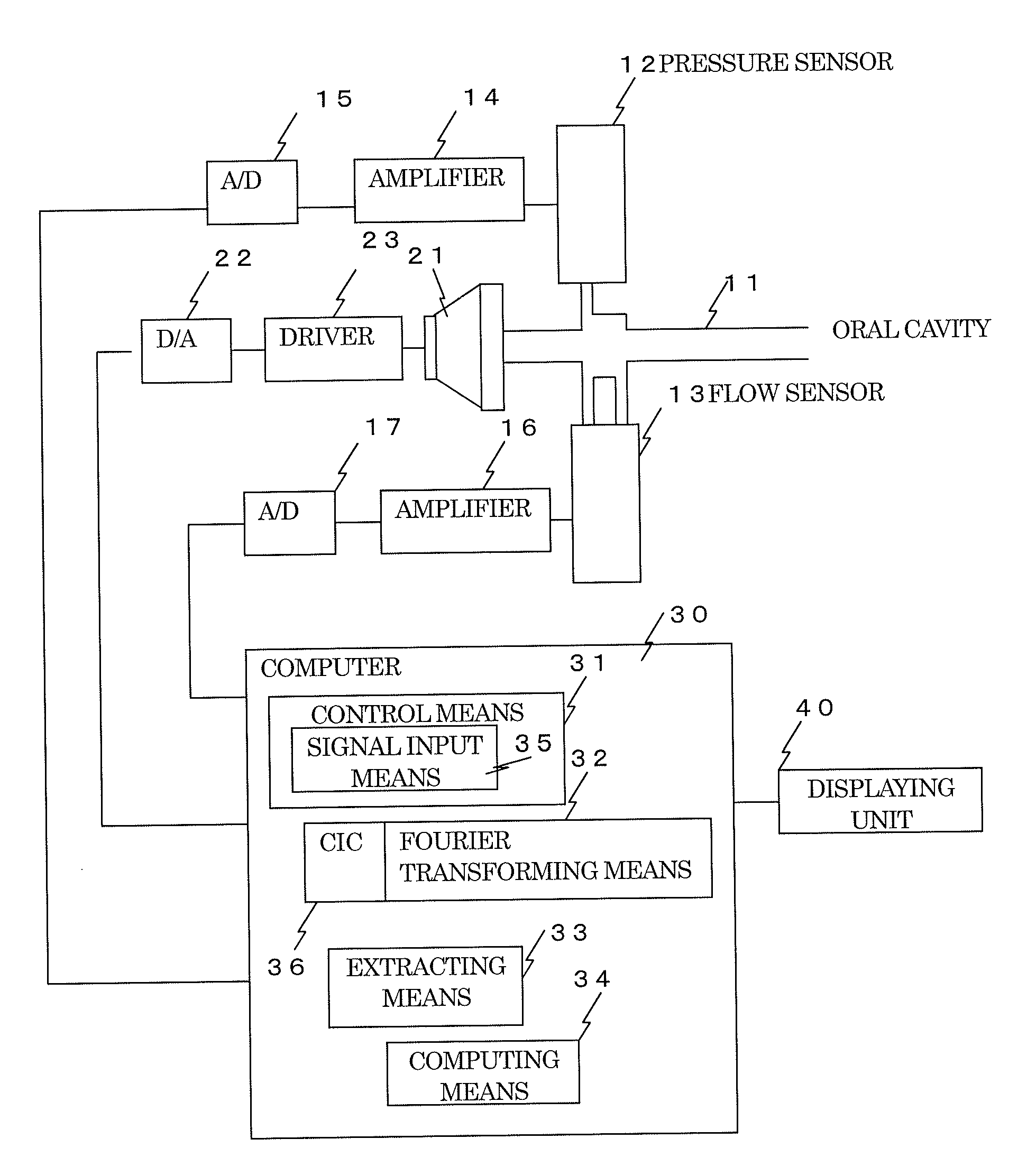
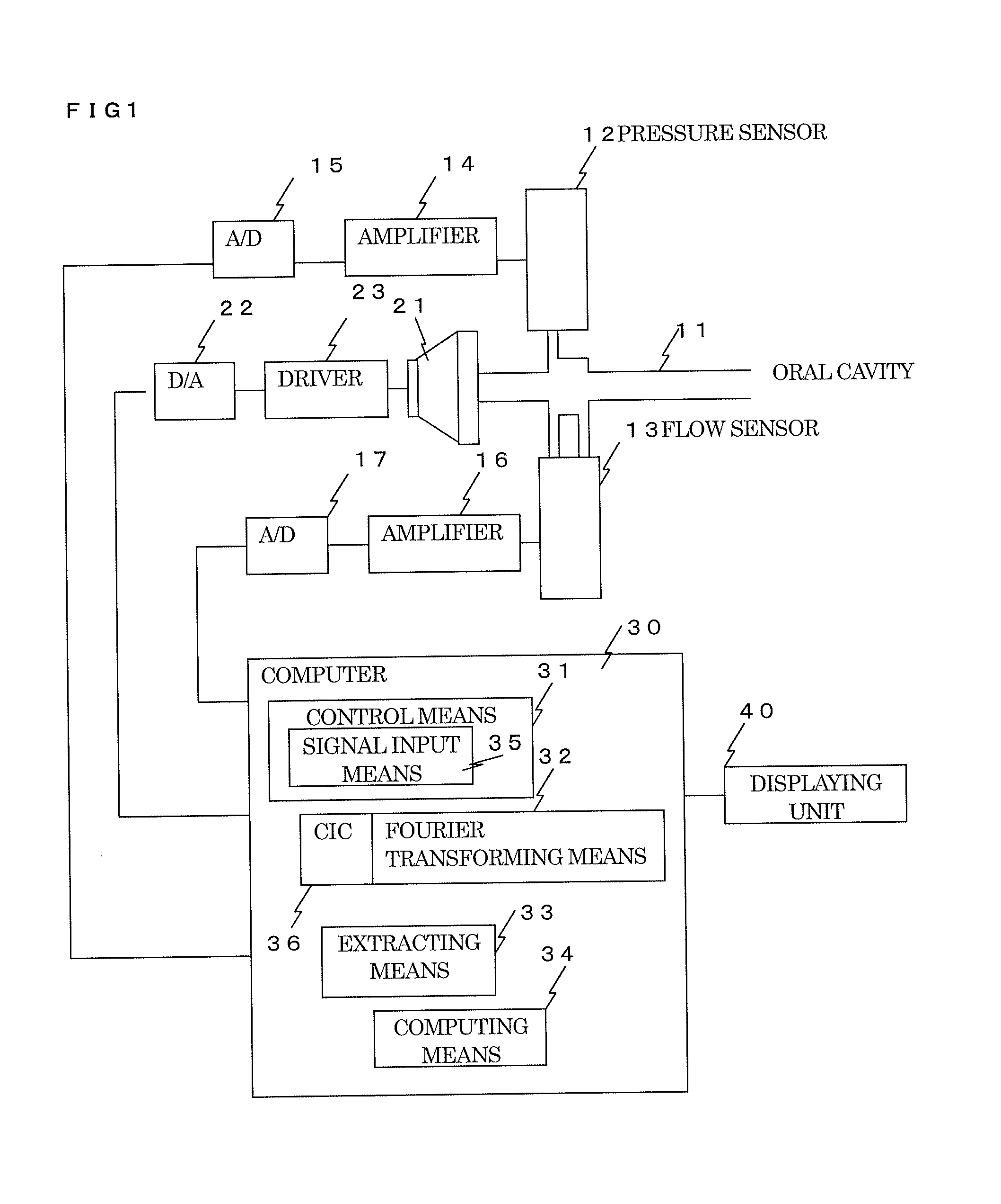
[0048]Embodiments of a respiratory impedance measuring apparatus and method according to the present invention will be described with reference to the accompanying drawings. FIG. 1 is a diagram of the configuration of the embodiment of the respiratory impedance measuring apparatus according to the present invention. The respiratory impedance measuring apparatus includes as its main components: a tube 11 whose tip is attached to an oral cavity of a human and through which a breathing flow flows; a pressure sensor 12 that is attached to the tube 11 and that makes up a pressure detecting means to detect the pressure in the oral cavity; a flow sensor 13 that makes up a flow detecting means of detecting the flow of breathing at the same position as that of the pressure sensor 12; a loudspeaker 21 that makes up a pressurizing means to apply an air vibration pressure to the inside of the oral cavity; and a computer 30.

[0049]An output signal of the pressure sensor 12 is amplified by an ampl...


PUM


Abstract

Continuous measurement of breathing impedance with extremely high precision is enabled by executing noise elimination. A loudspeaker 21 applies an air vibration pressure by an oscillation wave to an oral cavity, the oscillation wave being obtained by frequency-culling so executed that the oscillation wave has only the frequency component that is left after the culling is executed from a plurality of different frequencies and being generated by a pulse signal for pulse drive with pulses made positive and negative separately in correspondence to the time of exhalation and the time of inhalation. A pressure inside the oral cavity is detected and a breathing flow is detected, and a signal obtained by the detection is Fourier-transformed by a Fourier transforming means 32 to obtain a spectrum. A breathing high frequency component that contributes as a noise is obtained by an extracting means 33, using a spectrum that corresponds to a frequency component culled from the result of the Fourier transformation. This breathing high frequency component is subtracted from a spectrum that corresponds to a frequency component left by the culling to extract an oscillation wave component. Computing of dividing a pressure component by a flow component for each of frequencies for the result of this extraction is executed by a computing means 34 to obtain breathing impedance.

Description

TECHNICAL FIELD[0001]The present invention relates to a respiratory impedance measuring apparatus and method that are capable of continuously measuring a respiratory impedance of a human being, etc., and to a respiratory impedance display method.BACKGROUND ART[0002]Conventionally, an apparatus of this kind is known that includes a sine-wave pressurizing apparatus to apply as a load a sine-wave air vibration pressure to a respiratory system, an air current velocity detector to detect an air current velocity of the respiratory system, an air pressure detector to detect an air pressure of the respiratory system, and a resistance computing unit that calculates breathing resistance from the air current velocity and the air pressure detected by the air current velocity detector and the air pressure detector.[0003]The conventional apparatus: further includes a reference signal converter to convert a signal of the sine-wave air vibration pressure that is applied by the sine-wave pressurizin...

Claims


Application Information

Patent Timeline
Patent Type & Authority Applications(United States)
IPC IPC(8): A61B5/08
CPCA61M2230/46A61B5/682A61B5/087A61B5/7257A61B5/0809A61B5/038
Inventor KUROSAWA, HAJIMESHIMIZU, YOSHIOHOKI, TOSHIAKI
Owner CHEST CORP
Why Eureka
Try Eureka