
Retractable flow maintaining stent wire

a technology of stent wire and retractable flow, which is applied in the field of retractable flow maintaining stent wire, can solve the problems of balloon stents that have the diameter and flexibility to get into the cerebral circulation but cannot allow fluid flow when expanded, and the risk of bleeding is usually not high, so as to reduce the risk of bleeding and reduce the systemic tpa release

Inactive Publication Date: 2012-04-26
KLUCK BRYAN W
View PDF2 Cites 13 Cited by
  • Summary
  • Abstract
  • Description
  • Claims
  • Application Information

AI Technical Summary

Benefits of technology

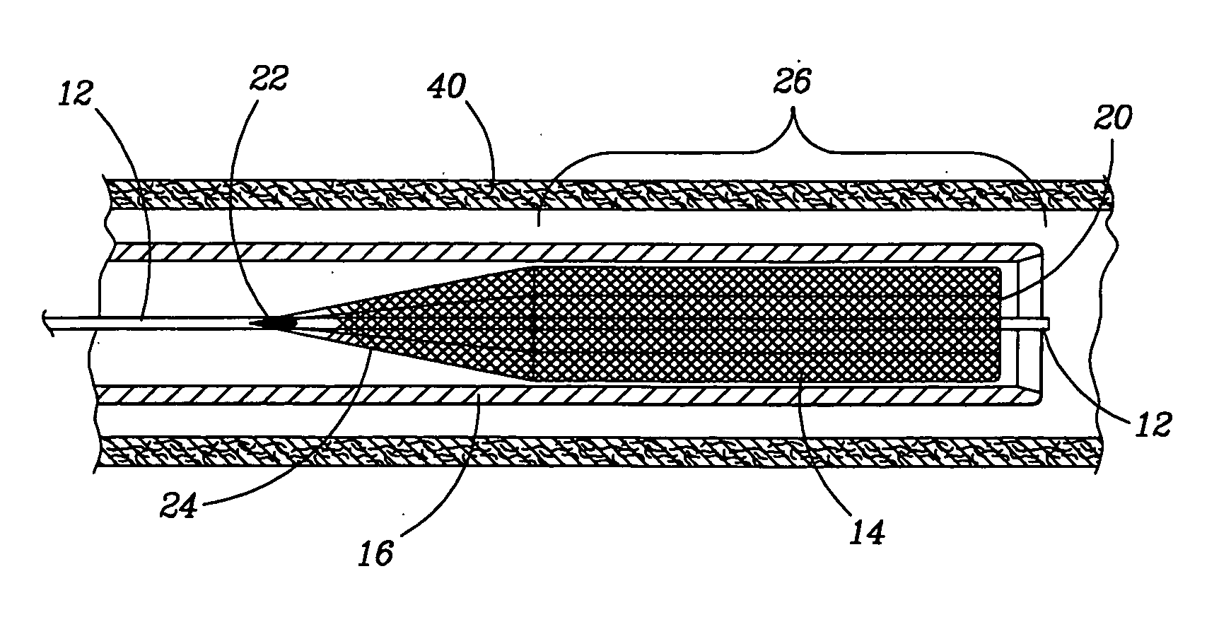
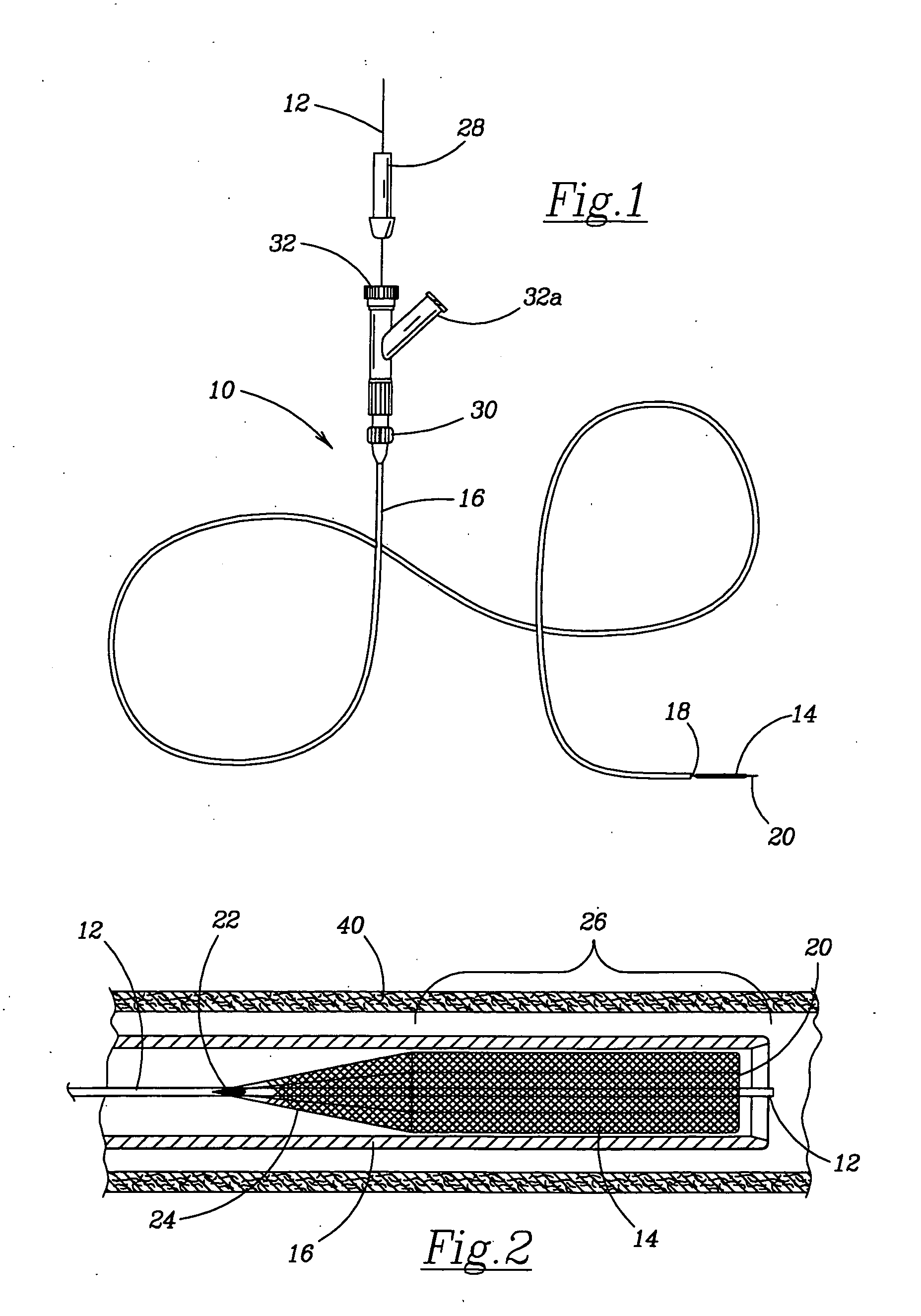
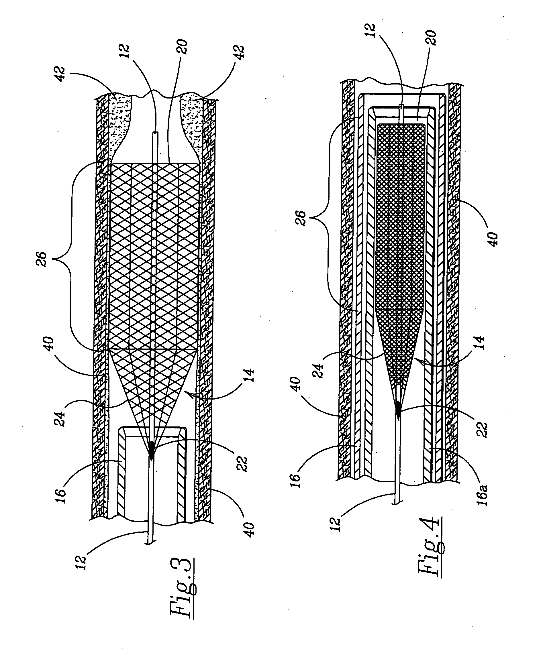
"The present invention is a self-expanding stent that can be delivered to the affected site in the human body with a guide wire and hand-manipulable control apparatus. The stent is designed to full expansion only along a pre-determined length of its body with the remainder of the overall length tapering to a fixed connection point with the guide wire. The stent is delivered to the affected area in a covering sheath that can be recaptured or retrieved by pulling it back into the sheath and withdrawing the stent wire completely from the vessel. The stent wire can be coated with suitable pharmaceutical agents to locally treat the area of the occlusion or obstruction, rather than give much larger doses of the same agent through the circulatory system, thus greatly reducing the risk of bleeding in the affected area, as well as other unintended locations in the body. The stent wire can also elute a lytic agent such as tissue plasminogen activator (tPA) or Urokinase directly on the obstructing thrombus, which can significantly reduce the systemic tPA release and also the downstream tPA that would flow to the injured tissue. The stent wire can be coated with a variety of therapeutic agents to aid in the treatment of the damaged tissue. The present invention is a stent wire device and manually controlled capture sheath of a sufficient size to allow for the constant access of a surgeon to the affected area, thus allowing further work to treat the affected area including but not limited to balloon, stent or other mechanical device delivery."

Problems solved by technology

Once deployed beyond the point where automatic expansion occurs, theses stents usually cannot be recaptured without risk of injury, if ever.
The balloon stents at present are of limited use in most delicate procedures because the high pressure inflations necessary to achieve full stent exposure is not possible in the intracranial vascular system due to its size and delicate arterial structure.
While they may restore the lumen, the balloons that have the diameter and flexibility to get into the cerebral circulations do not allow for fluid flow when expanded.
The problems with the current commercially available stents include: the potential for crushing from external pressure, risk of tearing the interior of vessel walls or penetrating a vessel wall upon retraction, and the inability to allow passage of the stent beyond an obstruction.
Additionally, drug eluting balloons mostly obstruct flow which limits their time in contact with the vessel wall and thus the effectiveness of the drugs.
None of these references, however, describe a means for relocating, retrieving or removing the stent once it is in position within a blood vessel or otherwise.
The potential for injury suggests that the wires of Rabkin may catch on the inner walls of the body vessel causing tears and bleeding during the retrieval process.
Nor do they disclose the capability of the stent to carry and be used in conjunction with pharmacological agents.
The connecting wire can traverse the entire body increasing risk of thrombus formation around the wire and distal embolization, and the onset of infection.
None of the existing stents have restricted expansion properties along their length limited by the proximal end being permitted to expand only into a conical, rather than substantially complete cylindrical, shape from the fixed connection to the axially positioned control wire, yet still permit the flow of bodily fluids through the partially expanded stent form, and have the capacity to be collapsed and be withdrawn without the need for recapture tools.

Method used


Image

  • Retractable flow maintaining stent wire
  • Retractable flow maintaining stent wire
  • Retractable flow maintaining stent wire

Examples


Embodiment Construction

[0031]The following detailed description is of the best presently contemplated mode of carrying out the invention. The description is not intended in a limiting sense, and is made solely for the purpose of illustrating the general principles of the invention. The various features and advantages of the present invention may be more readily understood with reference to the following detailed description taken in conjunction with the accompanying drawings.

[0032]Various embodiments of the retractable flow maintaining stent wire for delivering and retracting a self-expanding stent in accordance with the invention are described herein. Referring now to the drawings in detail, where like numerals refer to like parts or elements, there is shown in FIG. 1 a catheter 10 including a manifold 30 with a main port 32 and auxiliary port 32a. Mounted through the main port 32 is a guide wire 12 that exits through the manifold 30 and through the hollow shaft 16. At the distal end of the shaft 16 the ...


PUM


Abstract

The present invention is a self-expanding stent delivered to the affected site within the human body with a guide wire and hand-manipulable control apparatus. The stent is capable of full expansion only along a pre-determined length of its body with the remainder of the overall length tapering (in substantially conical form) to a fixed connection point with the guide wire. The stent is delivered to the affected area in a covering sheath that has a tip that is capable of penetrating a blockage or obstruction in a vessel such that the stent can be exposed to begin its expansion. Once the obstruction has been opened, the stent can be recaptured or retrieved by pulling it back into the sheath, collapsing the expanded stent, and withdrawing the stent and wire completely from the vessel. The present invention may be coated with a variety of therapeutic agents to aid in the treatment of the damaged tissue.

Description

BACKGROUND OF THE INVENTION[0001]This invention relates to a stent for use in a body passageway, comprising a flexible, self-expandable and retractable tubular wall with a guide wire and hand manipulable control apparatus.[0002]Use of expandable stents is known for treatment and repair of damaged areas of the circulatory system of the body such as blood vessels. They can be implanted in a patient's blood vessels to maintain the free unobstructed passage thereof. Stents have been used to reinforce weakened body lumens such as the urethra, bile ducts, blood vessels, the trachea, coronary arteries, and the esophagus. Stents are generally cylindrically shaped devices and are typically implanted within a vessel in a contracted state and expanded when in place in the vessel in order to maintain an unobstructed passage within the vessel to allow fluid flow through the vessel. As the stent is positioned it self-expands to conform to the inside contour of the vessel wall. The delivery system...

Claims


Application Information

Patent Timeline
Patent Type & Authority Applications(United States)
IPC IPC(8): A61F2/84A61F2/82
CPCA61M2025/09183A61M29/02
Inventor KLUCK, BRYAN W.
Owner KLUCK BRYAN W
Learn More