Unit for recovering and converting the thermal energy of the exhaust gases of an internal combustion engine of a vehicle

Active Publication Date: 2012-05-03
CENT RICERCHE FIAT SCPA
View PDF10 Cites 36 Cited by
  • Summary
  • Abstract
  • Description
  • Claims
  • Application Information

AI Technical Summary

Benefits of technology

[0013]The object of the present invention is that of overcoming the problems described above. In particular, the object of the present invention is that of providing a unit for recovering the thermal energy

Problems solved by technology

This aspect is particularly important due to the fact that, during a cold start, an engine does not operate under optimal lubrication conditions due to the high viscosity of the oil.
This, lastly, is susceptible of increasing frictions between the mobile parts of the engine and hence increase fuel consumption.
First, the layout of the system is typically quite cumbersome with respect to the space generally available inside an engine compartment of a vehicle, hence setting considerable restrictions related to the arrangement of the components.
However, advantages of such systems in terms o

Method used


Image

  • Unit for recovering and converting the thermal energy of the exhaust gases of an internal combustion engine of a vehicle
  • Unit for recovering and converting the thermal energy of the exhaust gases of an internal combustion engine of a vehicle
  • Unit for recovering and converting the thermal energy of the exhaust gases of an internal combustion engine of a vehicle

Examples


Embodiment Construction

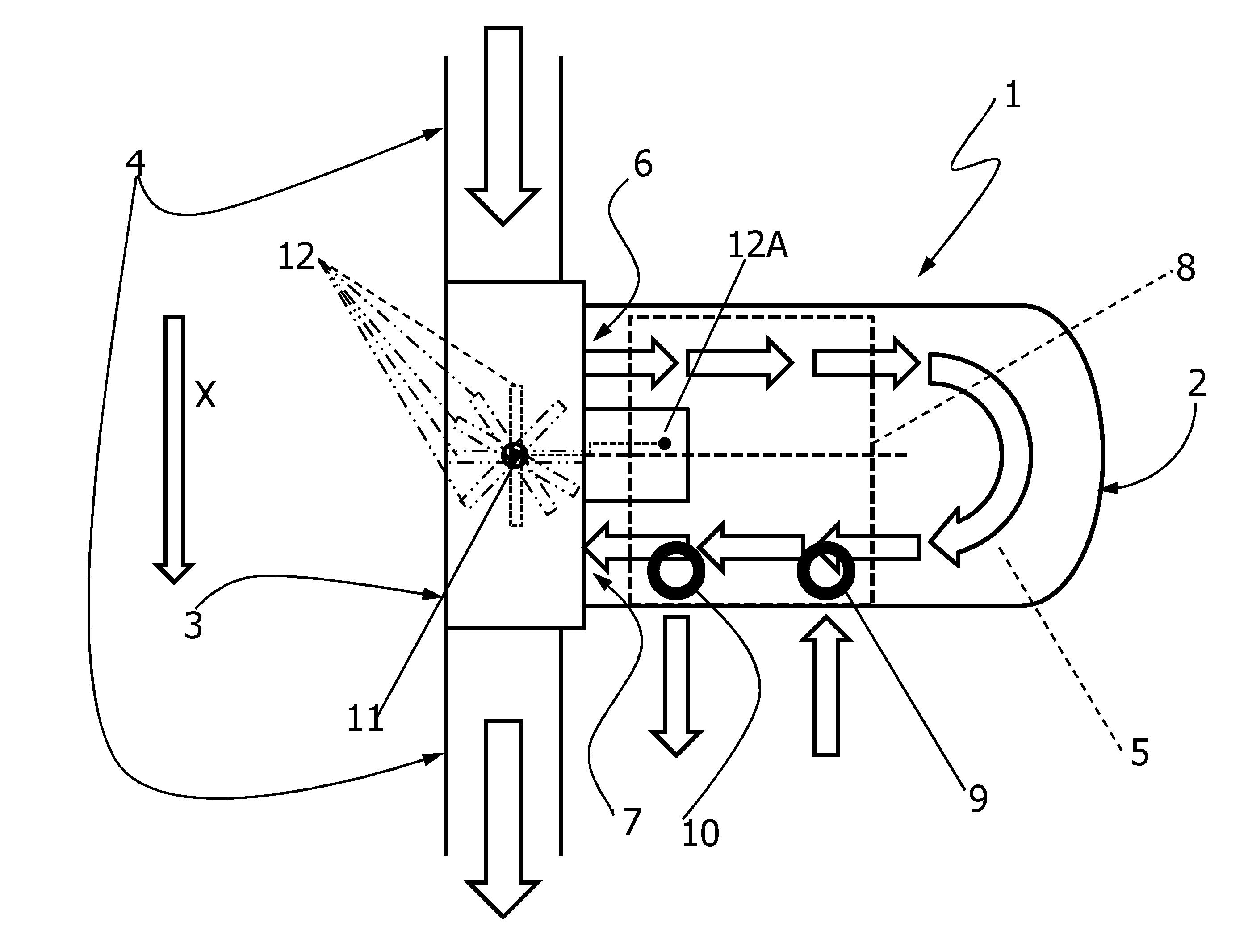
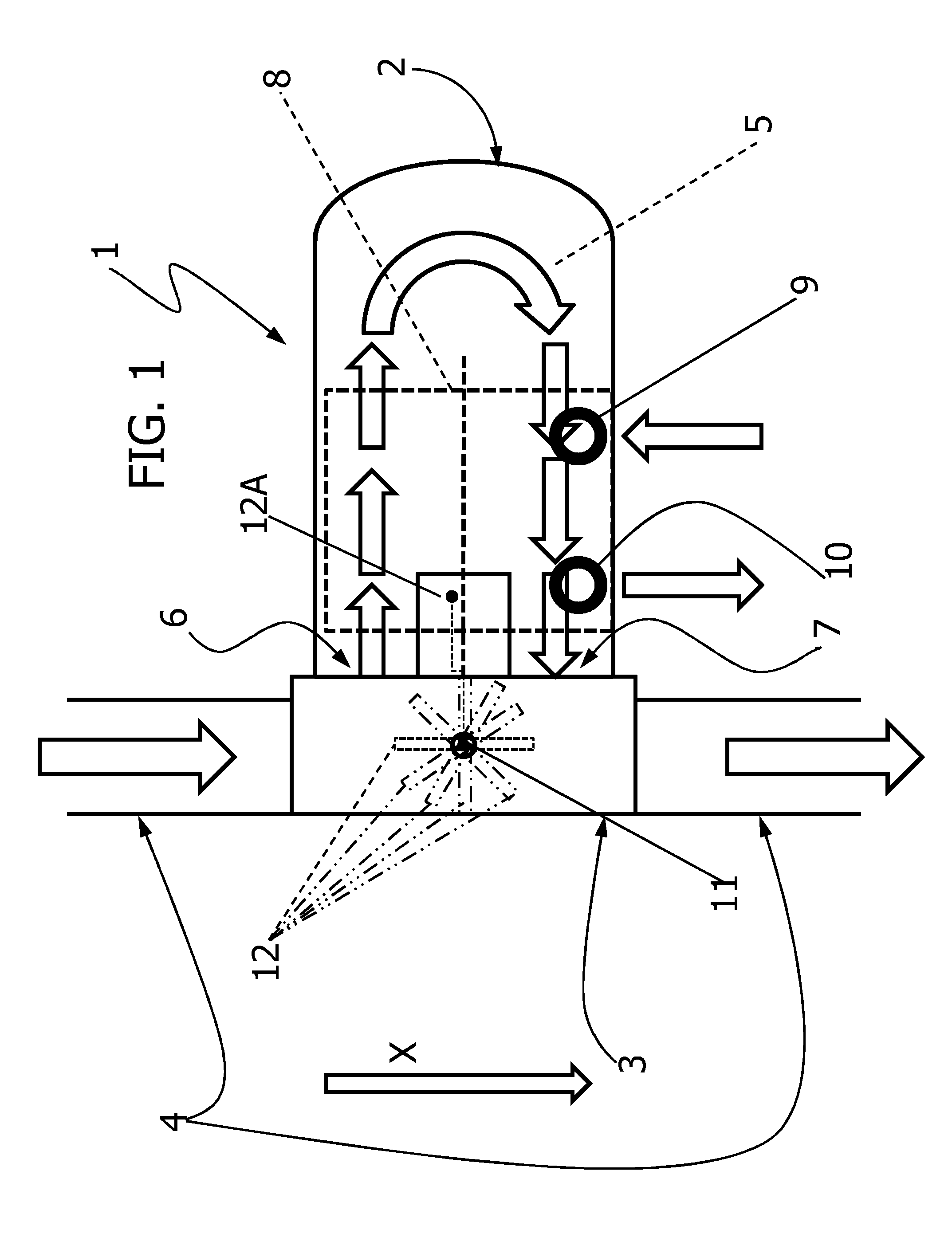
[0029]A unit for recovering and converting the thermal energy contained in the exhaust gases of an internal combustion engine according to the present invention is indicated with 1 in FIG. 1.

[0030]The unit 1 comprises a heat exchanger 2 connected, by means of an interface conduit portion 3, along an exhaust gas main line 4. The interface 3 is in form of an interface conduit portion interposed in the exhaust gas main line 4.

[0031]The exchanger 2 is of the so-called U-type, defining therein a substantially U-shaped path 5 for the exhaust gases, starting from an inlet section 6 of the heat exchanger and ending at an outlet section 7 of the heat exchanger. The inlet and outlet sections 6, 7 of the heat exchanger are located on the same side of the heat exchanger and both open on said interface conduit portion 3. As a result of this arrangement, the path 5 within the heat exchanger defines entirely in itself the by-pass path branching out from the exhaust gas main line 4.

[0032]The heat e...


PUM


Abstract

A unit (1, 1′) for recovering and converting thermal energy from the exhaust gases of an internal combustion engine (14) of a vehicle comprises a heat exchanger (2, 2′) to be traversed by exhaust gases flowing along a by-pass path (5,5′) branching out from an exhaust gas main line (4) of said internal combustion engine (14) and valve means (12) for controlling the flow of the exhaust gases through said path, said valve means (12) being driven by an actuator device (12A). The by-pass path (5, 5′) is a U-shaped path defined entirely within the heat exchanger (2, 2′),starting from an inlet section (6, 6′) and ending at an outlet section of the heat exchanger, the inlet and outlet sections (7,7′) being located on a same side of the heat exchanger (2) and both opening on an interface conduit portion (3) interposed in said exhaust gas main line (4). The heat exchanger (2, 2′) is arranged so that said U-shaped path is oriented transversely to the direction of the exhaust gas main line (4), in such a manner that the exhaust gases traversing the heat exchanger flow firstly in the transverse direction away from the exhaust gas main line (4) and then back in the transverse direction towards the exhaust gas main line (4), The valve means (12) are arranged within said interface conduit portion (3), between merging points of the inlet and outlet portions (6,7) of the heat exchanger (2,2′).

Description

FIELD OF THE INVENTION[0001]The present invention refers to a unit for recovering and converting thermal energy from the exhaust gases of an internal combustion engine of a vehicle, of the type comprising:[0002]a heat exchanger to be traversed by exhaust gases flowing along a by-pass path branching out from an exhaust gas main line of said internal combustion engine, and[0003]valve means for controlling the flow of the exhaust gases through said by-pass path, said valve means being driven by an actuator device.[0004]Units of this type are disclosed in EP 0 913 561 A2, US 2008 / 115487 A1 and EP 1 475 532 A2.GENERAL TECHNICAL PROBLEM AND DESCRIPTION OF THE PRIOR ART[0005]Over the last years, the automotive industry has been more and more oriented, in the design of engines, onboard systems and the vehicle itself, towards the reduction of fuel consumptions, pollutant emissions, recyclability of materials and, last but not least, the recovery and the conversion of the energy that would be...

Claims


Application Information

Patent Timeline
IPC IPC(8): F01N5/02
CPCF01M5/001Y02T10/166F01M11/0004F01M2011/0025F01N5/02F01N5/025F01N2240/02F01N2240/36F02G5/02F02G2260/00F02G2262/00F02M25/0731Y02T10/121Y02T10/16F01M5/002F02M26/28Y02T10/12
Inventor MAGNETTO, DANIELA
Owner CENT RICERCHE FIAT SCPA
Why Eureka
Try Eureka