Liquefied natural gas refueling system

a liquefied natural gas and refueling technology, applied in the direction of mechanical equipment, vessel construction details, container discharging methods, etc., can solve the problems of subcooled liquid thwarting standard pressure building methods, requiring non-standard operation of bulk cryogenic storage tanks, and difficult to maintain minimum pressur

Inactive Publication Date: 2012-05-03
LINDE AG
View PDF1 Cites 10 Cited by
  • Summary
  • Abstract
  • Description
  • Claims
  • Application Information

AI Technical Summary

Benefits of technology

[0024]The refueling arrangement where refueling is direct to the customer's storage tanks or to the vehicle fuel tanks may employ multiple additional elements for efficient operation. Pressure and flow control logic may be employed to signal when the refueling operation is complete. Additional piping may be employed to route at least a portion of the excess gas that may be present at the beginning of the refueling, or produced during refueling, back to the bulk storage tank.

Problems solved by technology

This minimum pressure has proven difficult to maintain because LNG in a bulk storage tank has a temperature which may be well below the saturation temperature at the desired onboard fuel tank pressure (i.e., subcooled).
However, in a typically horizontal, relatively small, and constantly moving onboard fuel tank, the subcooled liquid will thwart standard pressure building methods.
It is a relatively expensive and time consuming technique that requires a non-standard operation of a bulk cryogenic storage tank.
Other serious problems are that it introduces inflexibility into the refueling system operation and increases the likelihood that excess pressure natural gas will be vented from the bulk storage tank.
For the latter situation, the ‘saturation’ step is not only unnecessary, but it is detrimental to the density of the LNG inside the onboard fuel tank, as well as the amount of time the LNG can be stored in the onboard fuel tank without venting.
The system of the '088 patent also has a number of complexities that would make it impractical for stable control during the highly transient operation of a refueling system.

Method used


Image

  • Liquefied natural gas refueling system
  • Liquefied natural gas refueling system
  • Liquefied natural gas refueling system

Examples


Embodiment Construction

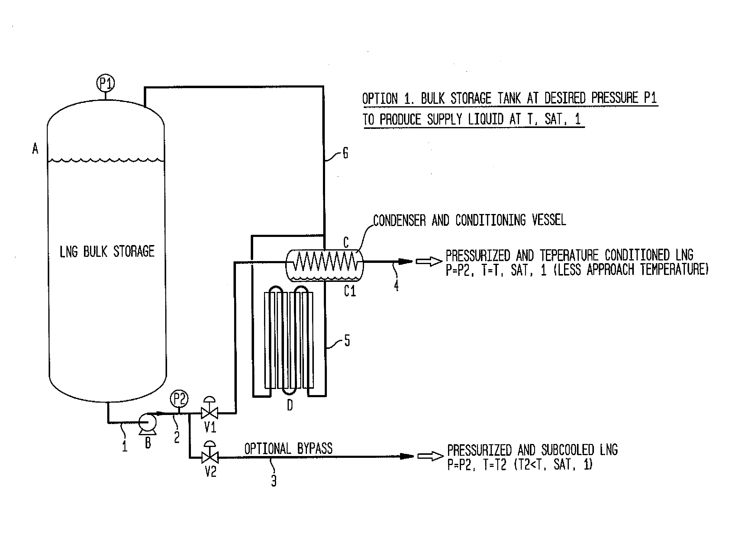
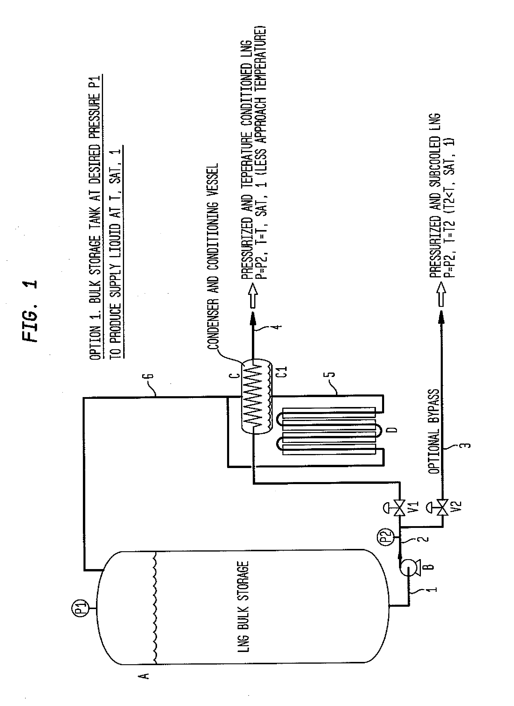
[0028]The invention provides an inherently stable, and quickly adjustable, method for producing LNG at specified temperatures and pressures. In one embodiment, detailed in FIG. 1, a LNG distribution system is shown. The bulk storage tank A is maintained at pressure P1 through standard tank pressure control methods, not shown in the figure. The pressure P1 may vary somewhat over time in order to minimize unnecessary venting of natural gas vapor. A typical bulk storage tank pressure is about 4 to 12 barg. The liquefied natural gas will exit the bulk storage tank A through line 1 and pump B. The liquefied natural gas now at pressure P2 which is higher than pressure P1 passes through valve V1 by line 2 and into condenser C which is in a heat transfer relationship with conditioning vessel C1. The liquefied natural gas will exit the condenser C through line 4 at the pressure P2 and at a temperature that is higher than the temperature before it entered the condenser C. This exit temperatur...


PUM

PropertyMeasurementUnit
temperatureaaaaaaaaaa
saturation temperatureaaaaaaaaaa
pressuresaaaaaaaaaa

Abstract

A method and apparatus for supplying liquefied natural gas to a storage tank or a fuel tank at specified temperatures and pressures. The method employs the steps of pressurizing a conditioning vessel with gaseous natural gas at a first pressure, feeding liquefied natural gas at a second pressure greater than the first pressure to a condenser in heat transfer relationship with the conditioning vessel, and withdrawing the liquefied natural gas from the condenser.

Description

CROSS REFERENCE TO RELATED APPLICATIONS[0001]This application claims priority from U.S. patent application Ser. No. 61 / 351,028 filed Jun. 3, 2010.BACKGROUND OF THE INVENTION[0002]The invention provides for a method and apparatus to supply liquefied natural gas at a specified but adjustable temperature and pressure. More particularly, the invention is particularly useful for refueling onboard vehicle fuel tanks.[0003]Liquefied natural gas (LNG) is composed primarily of methane, which comprises about 85 to 99% of the natural gas on a molar basis. Lesser components that may be present include ethane, propane, carbon dioxide, oxygen and nitrogen. For the purposes of illustration, the properties of pure methane will be used to characterize LNG.[0004]LNG vehicle fuel tanks typically require a minimum storage pressure of about 6-10 barg in order to deliver the fuel to the engine without the assistance of a pump. This minimum pressure has proven difficult to maintain because LNG in a bulk s...

Claims


Application Information

Patent Timeline
Patent Type & Authority Applications(United States)
IPC IPC(8): F17C7/02
CPCF17C9/02F17C7/02F17C7/04F17C2201/054F17C2203/0329F17C2203/0391F17C2221/011F17C2221/014F17C2221/016F17C2221/033F17C2223/0161F17C2223/0169F17C2225/0169F17C2227/0107F17C2227/0135F17C2227/0311F17C2227/0339F17C2227/0372F17C2250/01F17C2250/0626F17C2260/024F17C2265/035F17C2265/065
Inventor LEE, RON C.HEISCH, PHILIPPE
Owner LINDE AG
Why Eureka
Try Eureka