
Flexible EMAT Arrays for Monitoring Corrosion and Defect Propagation in Metal Components and Structures

a technology of metal components and flexible emat arrays, which is applied in the direction of instruments, specific gravity measurement, measurement devices, etc., can solve the problems of inability to inability to use piezoelectric transducers that generate sh waves and measure the remaining thickness of a plate or pipe wall in many cases, and inability to reliably and expensively. , to achieve the effect of easy attachment, increased sensitivity and resolution, and low profil

Inactive Publication Date: 2012-05-03
LOPEZ JAUREGUI BORJA
View PDF8 Cites 57 Cited by
  • Summary
  • Abstract
  • Description
  • Claims
  • Application Information

AI Technical Summary

Benefits of technology

[0013]Emphasis is placed on printed or etched circuit sensor coil designs that are attached to and covered with thin, flexible and insulating substrates. This construction provides for consistent and reliable EMAT performance in demanding production environments. The arrays include linear and two-dimensional (2-D) arrays of circular spiral coils, elongated spiral (racetrack) coils and rectangular spiral coils for generating and detecting radial polarized and linear polarized SH bulk waves. Dual-rectangular (butterfly) coils for generating and detecting linear polarized compression waves as well as linear polarized SH bulk and plate waves are described.
[0014]A salient feature of said printed circuit sensor coil designs is the plated-through hole in the flexible substrate. said plated through holes are used to connect multiple layers of concentric coils for increased sensitivity and resolution while maintaining a low profile for easy attachment to a test component and reliable performance in harsh environments. The multilayer construction afforded by said plated through holes also facilitates the design and fabrication of high density linear and 2-D Arrays for increased sensitivity and resolution. This configuration consists of an array of adjacent coils that are etched on one substrate and an array of overlapping coils that are etched on opposite sides of said substrate. Also, said arrays of coils can be insulated from each other by a cover layer and attached to form two arrays of overlapping coils. Using this construction, defects in the test components are interrogated with twice as many EMAT sensor coils. This results in an improvement in resolution and sensitivity by a factor as much as four over the single array design.
[0015]Various permanent magnet and electromagnet assembly designs are used to provide the magnetic bias fields for the each of the EMAT sensor coil arrays. Cylindrical magnets are linked together in flexible linear arrays or are molded to conform to the contour of the component under interrogation and are installed over the linear arrays of spiral coils to facilitate the generation of radial polarized SH waves. Block magnets are linked together in flexible linear arrays or are molded to conform to the contour of the component under interrogation and installed over the linear arrays of racetrack, rectangular or butterfly coils to facilitate the generation of linearly polarized SH waves. U-shaped magnets with opposite poles are linked together in flexible linear arrays and installed over the linear arrays of butterfly coils to facilitate the generation of linear polarized compression waves. Larger U-shaped magnets are used to induce magnetic fields that have a component that is parallel to the surface of the test component and to the electrical conductors of the EMAT coils.
[0016]EMAT arrays are designed and fabricated with coils, electrical connections and magnets that can withstand temperatures of the test component in excess of 600 degrees C. Copper coils are etched on thin sheets of insulating materials such as flexible ceramics. The coils are covered with electrical and thermal insulating sheets. The insulating sheets are covered with thin electrically conducting strips, e.g., metals, on the side that is opposite the coil to reflect heat radiation from the test component. Similarly insulating sheets coated with said strips are installed between the coils and magnets and connected to heat sinks to prevent the coils and magnets form reaching excessive temperature. Layers of ferromagnetic insulators can be installed between this thermally insulating sheet to prevent eddy current induction and resultant ultrasonic waves in the magnet poles.

Problems solved by technology

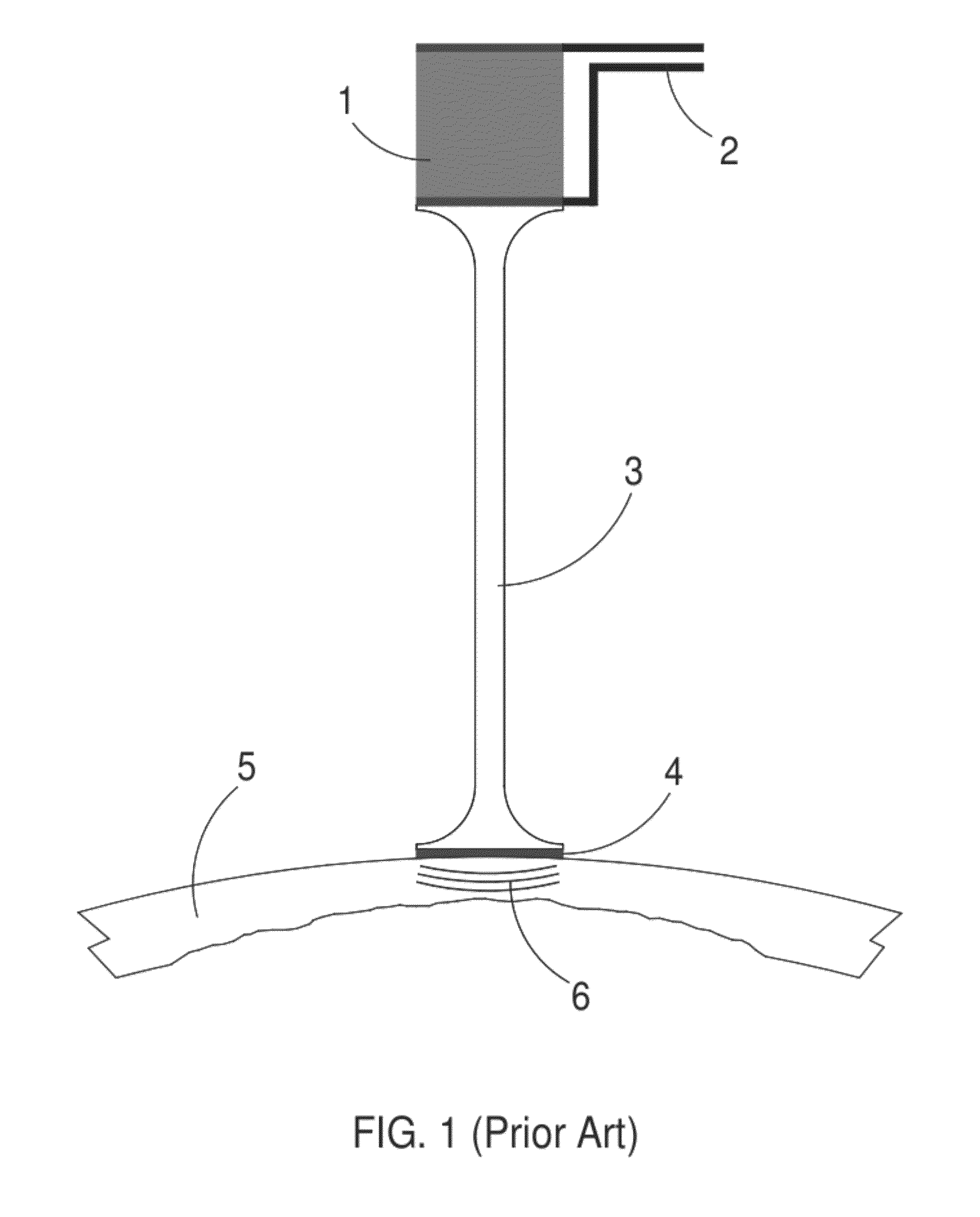
The use of arrays of piezoelectric crystals with wave guides can be difficult, unreliable and expensive.
The use of piezoelectric transducers that generate SH waves and measure the remaining thickness of a plate or pipe wall is in many cases not practical.
Since SH waves can be transmitted and detected by piezoelectric transducers only if the wave guide is bonded or coupled to the test component through a viscous media, SH wave inspection with piezoelectric transducers at elevated temperatures is not practical.

Method used


Image

  • Flexible EMAT Arrays for Monitoring Corrosion and Defect Propagation in Metal Components and Structures
  • Flexible EMAT Arrays for Monitoring Corrosion and Defect Propagation in Metal Components and Structures
  • Flexible EMAT Arrays for Monitoring Corrosion and Defect Propagation in Metal Components and Structures

Examples


Embodiment Construction

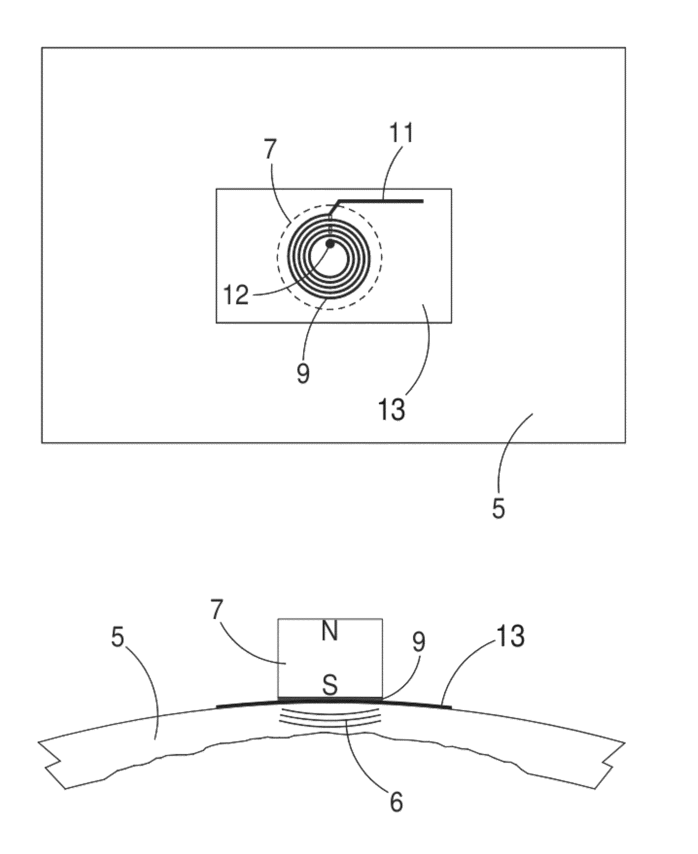
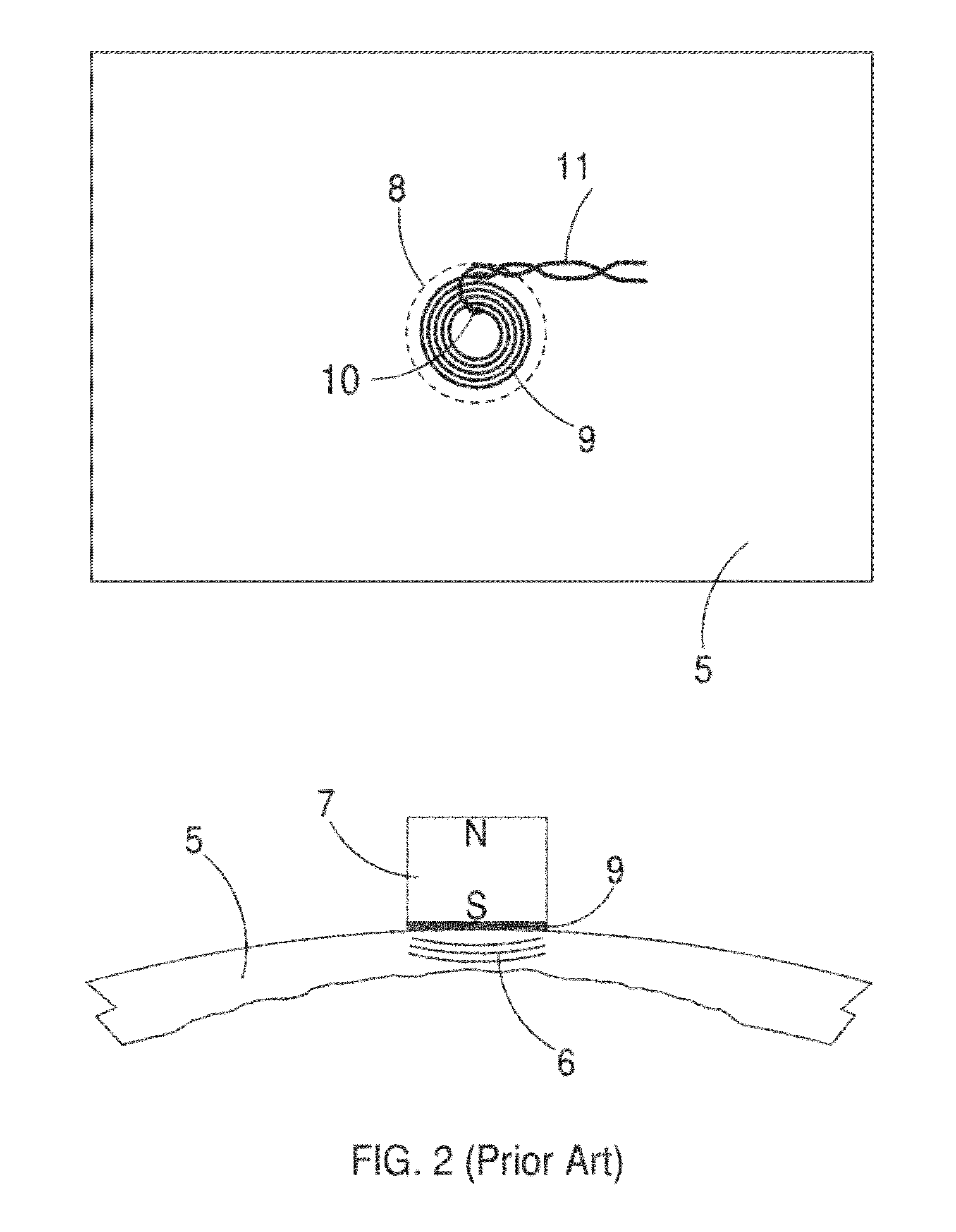
[0050]FIG. 3 illustrates an EMAT configuration that is used to generate and detect radial, horizontal-polarized bulk shear waves, 6, that propagate in a direction that is normal or perpendicular to the test component material, 5, surface. A magnet, 7, produces a magnetic field that is also normal to the metal part under test. A circular spiral coil, 9, is composed of insulated electrical conductors that are chemically etched or machined to from an electrical conducting plated coil that adheres to a substrate, 13, of insulating materials such as polyimides and ceramics. Said coils are placed in a position that is within the boundaries, 8, of the magnet poles.

[0051]Said circular spiral coil is composed of electrical conducting material including but not limited to copper, silver and gold. Said coils can be fabricated so that each coil consists of two or more layers where said coils in each layer are concentric to coils in the other layers. Said coils in each layer are electrically con...


PUM


Abstract

The invention pertains to the design, arrangement and fabrication of arrays of electromagnetic acoustic transducers (EMATs) for detection and monitoring of defects in metal components while they are being used in service. Emphasis is placed on printed circuit sensor coil designs that are attached to and covered with thin, flexible and insulating substrates. This laminated construction with additional means for electrical and thermal insulation, radiation heat shielding and simple cooling provides for consistent and reliable EMAT performance in monitoring components at elevated temperatures. The arrays include circular spiral coils, elongated spiral (racetrack) coils and rectangular spiral coils. Also described are arrays of dual-rectangular (butterfly) coils, meander coils and trapezoidal coils. Various assembly designs for the attachment of bias magnets are described.

Description

TECHNICAL FIELD AND BACKGROUND OF THE INVENTION[0001]The field of this invention relates to the maintenance of structural and fluid transmission components in industrial facilities, naval vessels and gas and liquid transportation infrastructure by continuously monitoring the propagation of corrosion and certain defects in these structures. Specific applications include the measurement of wastage corrosion in pipe elbows, corrosion at the base of storage tanks, internal fissures in pressure vessels and stress corrosion cracks in and near various welds.[0002]These applications are performed by attaching an array of EMATs to the test component and periodically transmitting, receiving, detecting and processing of reflections of ultrasonic waves. The time of flight and in some cases the amplitude of the reflected waves provides a measure of the extent of defect propagation. Also, a comparison of the immediate, reflected ultrasonic wave signal response to previous responses indicates the ...

Claims


Application Information

Patent Timeline
IPC IPC(8): G01N29/04
CPCG01N29/2412G01N2291/106G01N2291/0234G01N29/262
Inventor LOPEZ JAUREGUI, BORJA
Owner LOPEZ JAUREGUI BORJA
Learn More