Plastic bottle

a plastic bottle and bottle body technology, applied in the field of containers, can solve the problems of crazing effect, permanent deformation, low or light weight plastic bottles, etc., and achieve the effect of improving impact resistance and reducing or eliminating damag

Inactive Publication Date: 2012-05-03
COLGATE PALMOLIVE CO
View PDF2 Cites 12 Cited by
  • Summary
  • Abstract
  • Description
  • Claims
  • Application Information

AI Technical Summary

Benefits of technology

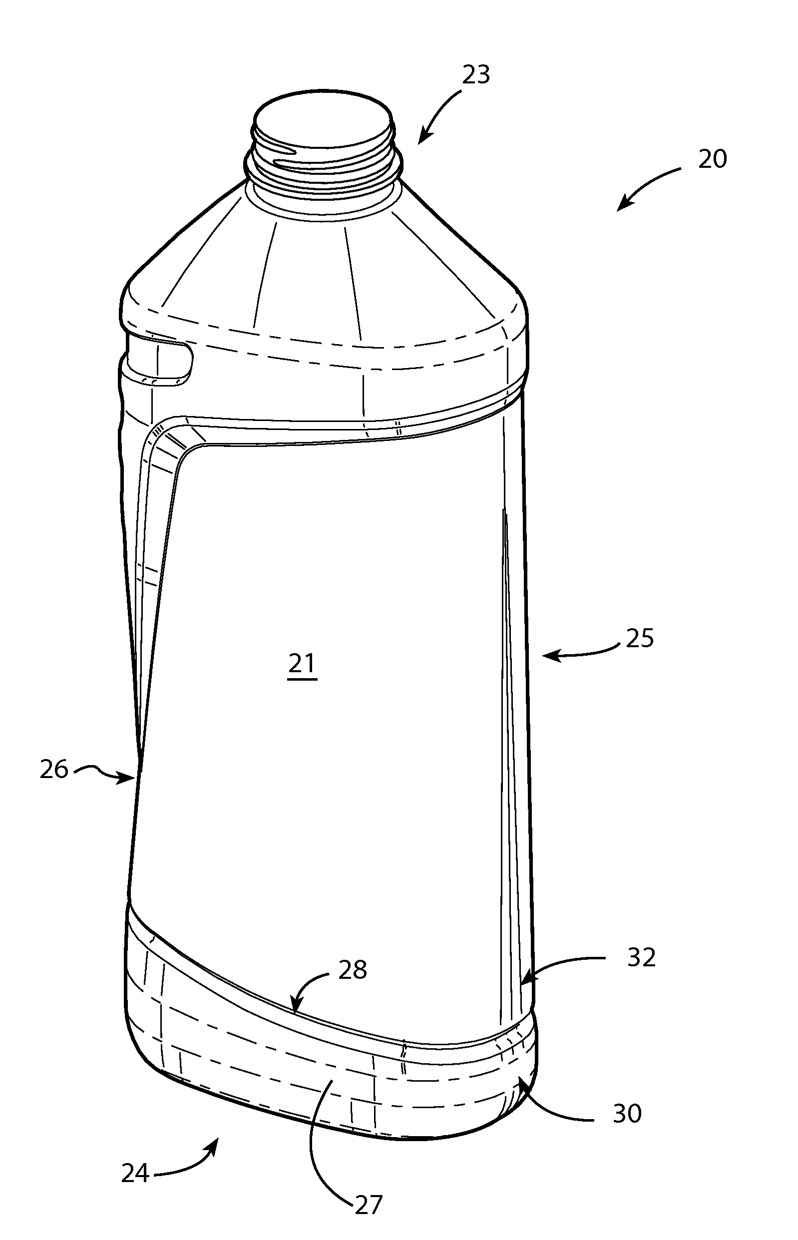
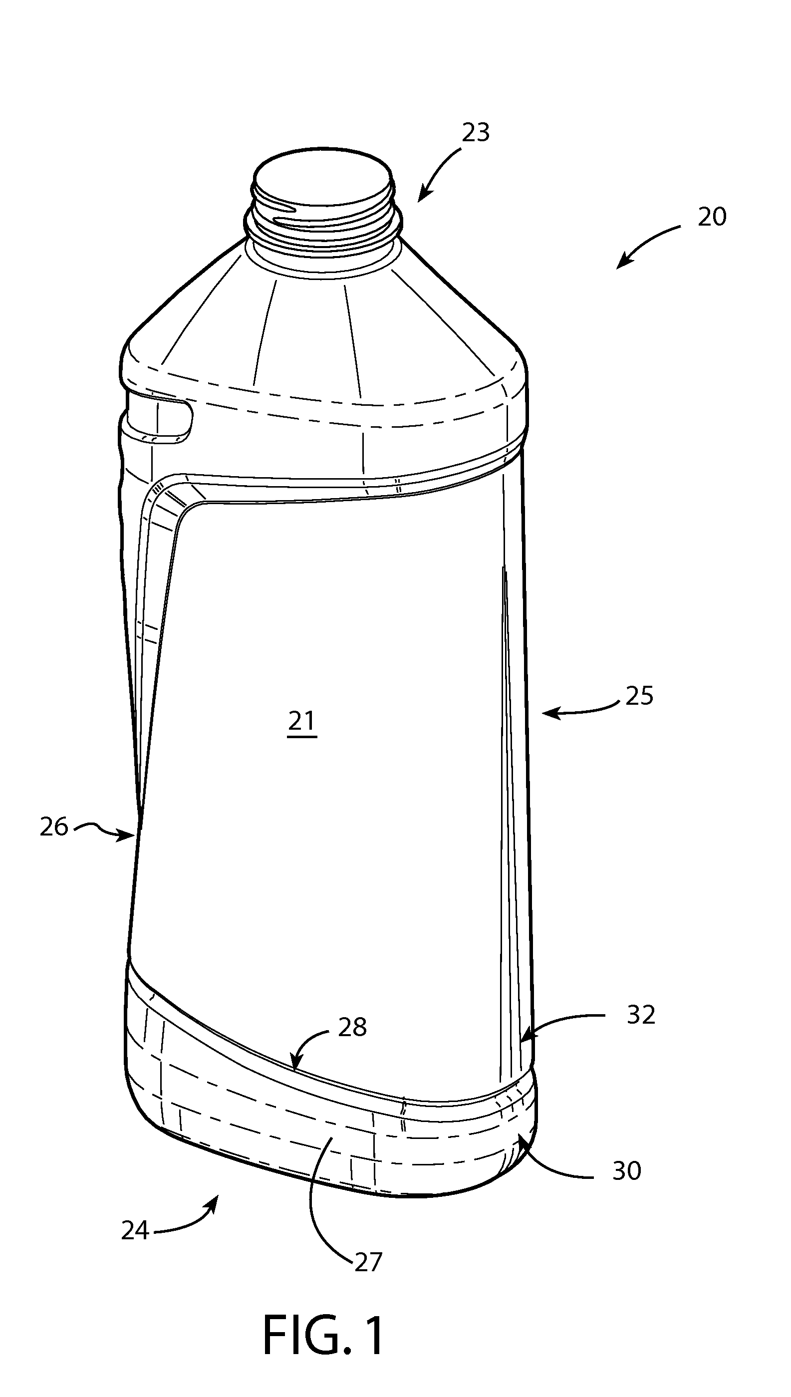
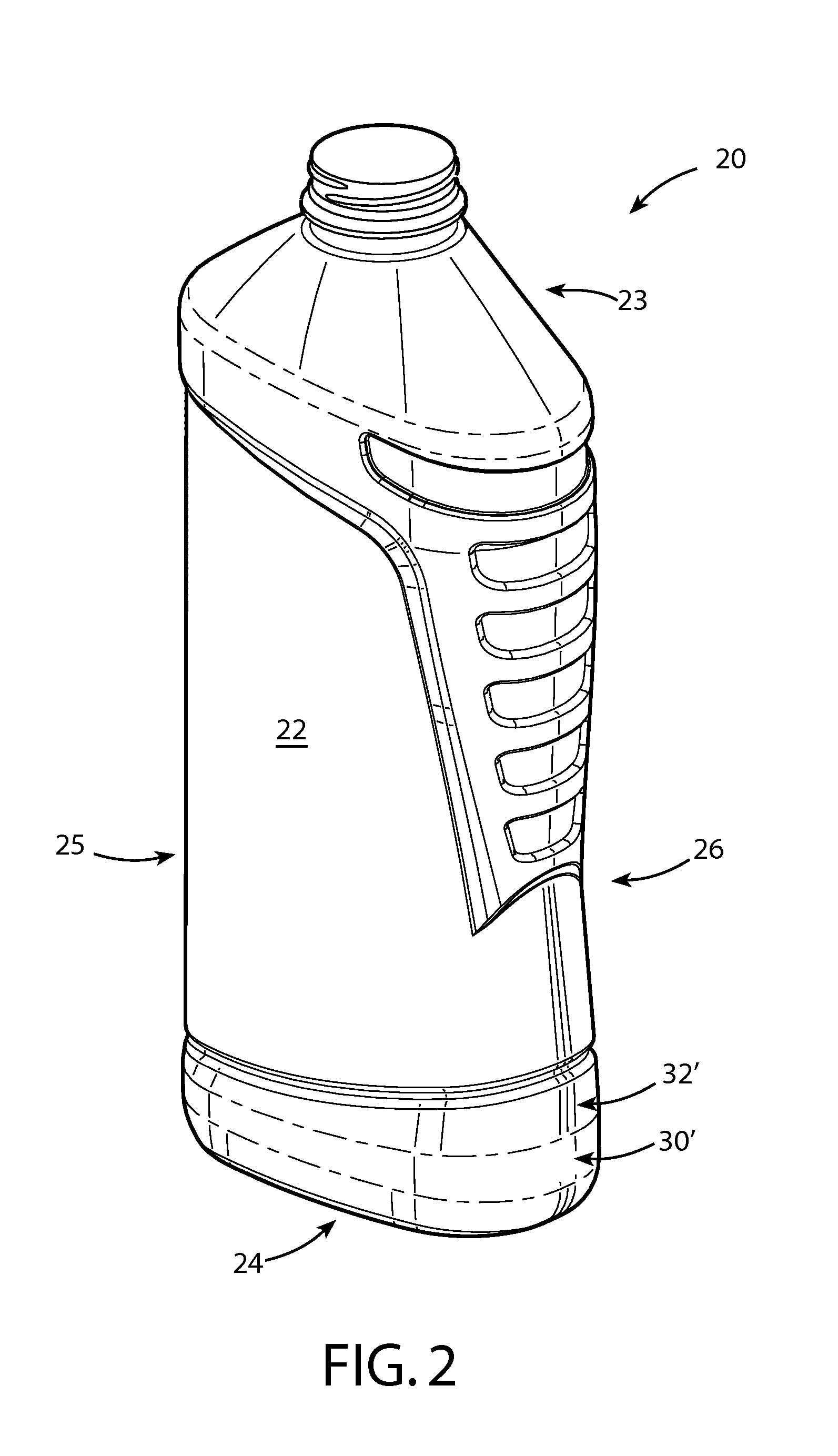
[0009]A light weight, thin-walled plastic flat container such as a bottle with improved impact resistance is provided that is configured and adapted to reduce or eliminate damage resulting from handling on high speed product processing lines. In one embodiment, a bottle according to the present invention includes first and second primary contact regions or bearing surfaces disposed on opposite narrow (i.e. small or short depth) sides of the bottle. In some embodiments, the bottle further preferably includes third and fourth secondary contact regions or bearing surfaces disposed on the same opposite narrow sides of the bottle. Preferably, the primary bearing surfaces are spaced apart from and located at a different elevation on the narrow sides of the bottle than the secondary contact surfaces. Both the primary and second bearing surfaces are each preferably located respectively at the same elevation on the bottles.

Problems solved by technology

There is an increasing challenge for producing low or light weight plastic bottles for use such as in liquid packaging.
All the more, PET is more rigid than polyolefins, leading more easily to permanent deformation, or deformation with resilience but leaving visible white traces or lines on the material (so-called crazing effect) which is not aesthetically pleasing to consumers.
Therefore, with these foregoing technology evolutions, having low weight PET flat bottles on a high speed product line leads to new issues with bottle impact resistance and handling on process line conveyors.
Either of these two effects are not acceptable in the scope of usual production quality.

Method used


Image

  • Plastic bottle
  • Plastic bottle
  • Plastic bottle

Examples


Embodiment Construction

[0027]This description of illustrative embodiments according to principles of the present invention is intended to be read in connection with the accompanying drawings, which are to be considered part of the entire written description. In the description of embodiments of the invention disclosed herein, any reference to direction or orientation is merely intended for convenience of description and is not intended in any way to limit the scope of the present invention. Relative terms such as “lower,”“upper,”“horizontal,”“vertical,”“above,”“below,”“up,”“down,”“top” and “bottom” as well as derivative thereof (e.g., “horizontally,”“downwardly,”“upwardly,” etc.) should be construed to refer to the orientation as then described or as shown in the drawing under discussion. These relative terms are for convenience of description only and do not require that the apparatus be constructed or operated in a particular orientation. Terms such as “attached,”“affixed,”“connected,” and “interconnect...


PUM

PropertyMeasurementUnit
thicknessaaaaaaaaaa
thicknessaaaaaaaaaa
depthaaaaaaaaaa

Abstract

A light weight flat container such as a bottle (20) formed of an elastically deformable plastic material and having a staged load bearing system including primary and secondary load bearing surfaces. The bottle includes two op posing wide sides (21, 22) and two opposing narrow sides (25, 26) on which the load bearing surfaces may be disposed. A base (27) is provided which protrudes beyond the narrow sides (25, 26) in some embodiments. During processing of the bottles on a conveyor fill line, mating primary load bearing surfaces (30, 30′) on adjacent bottles initially engage and begin to deform under contact forces. The mating secondary load bearing surfaces (32, 32′) next engage to better distribute the contact forces and control deformation of the bottles to below the elastic limit of the plastic material to avoid plastic deformation or crazing damage to the bottles when the contact forces subsides. A bottle processing method is also provided.

Description

CROSS-REFERENCE TO RELATED PATENT APPLICATIONS[0001]The present application claims the benefit of U.S. Provisional Patent Application No. 61 / 224,564, filed Jul. 10, 2009, the entirety of which is hereby incorporated by reference.BACKGROUND[0002]The present invention relates generally to containers, and more particularly to low or light weight plastic bottles.[0003]There is an increasing challenge for producing low or light weight plastic bottles for use such as in liquid packaging. This is driven by cost and sustainability. This demand is being fulfilled for cylindrical or square bottles, such as those used for bottled water or other beverages and other products. Nevertheless, there remains a need for light weight flat bottles, such as without limitation those used in product categories including home care products, personal care packaging, and others. Flat bottles are those for which the foot print or base shows a significant minor axis—major axis difference, typically higher than ...

Claims


Application Information

Patent Timeline
Patent Type & Authority Applications(United States)
IPC IPC(8): B65D90/02B29C65/20
CPCB65D1/0223
Inventor FONTANA, CAROLINE
Owner COLGATE PALMOLIVE CO
Why Eureka
Try Eureka