Signal level adjusting device and high-frequency apparatus

a technology of signal level adjustment and high-frequency apparatus, which is applied in the direction of pulse automatic control, oscillation generator, amplification control details, etc., can solve the problems of not revealing a method to solve the above-described problem, and the disturbance of image and sound occurs due, so as to avoid an adverse effect, suppress spurious, suppress spurious output of variable attenuator

Active Publication Date: 2012-05-03
NIHON DEMPA KOGYO CO LTD
View PDF1 Cites 5 Cited by
  • Summary
  • Abstract
  • Description
  • Claims
  • Application Information

AI Technical Summary

Benefits of technology

[0019]The present invention provides, in the signal level adjusting device in which the signal level on the output side of the variable attenuator provided in the signal path of the frequency signal is detected, and the control voltage for adjusting the attenuation amount of the variable attenuator is output, in accordance with the detection voltage, from the control unit via the digital / analog converter, to make the signal level of the output of the variable attenuator constant, the low-pass filter between the output side of the digital / analog converter and the variable attenuator, to thereby cut a frequency component corresponding to an overshoot generated when the output of the digital / analog converter is changed. Further, the control voltage is designed to be output from the control unit at a time interval longer than the time constant of the low-pass filter determined by the cut-off frequency of the low-pass filter so that no influence is exerted on a control operation. Accordingly, it is possible to suppress a spurious due to the change in the output of the digital / analog converter.
[0020]The another invention uses, in the signal level adjusting device in which the signal level on the output side of the variable attenuator provided in the signal path of the frequency signal is detected to output the control voltage for adjusting the attenuation amount of the variable attenuator in accordance with the detection voltage, the comparator without using the D / A converter, and it provides the low-pass filter on the output side of the comparator to generate the control voltage, which provides an effect that the spurious in the output of the variable attenuator can be suppressed.
[0021]Further, if such a signal level adjusting device is applied to the high-frequency apparatus such as the frequency synthesizer, for example, it is possible to avoid an adverse effect due to the spurious.

Problems solved by technology

However, the aforementioned frequency synthesizer has a problem as follows.
However, in a frequency synthesizer used in an OFD system for terrestrial digital broadcasting with 64QAM modulation, for example, disturbance of image and sound occurs due to the spurious.
Although Patent Document 1 describes a technology in which weighting processing is performed on an output of a voltage controlled attenuator to create a control voltage and the control voltage is supplied to the voltage controlled attenuator via a D / A converter, it does not disclose a method for solving the above-described problem.

Method used


Image

  • Signal level adjusting device and high-frequency apparatus
  • Signal level adjusting device and high-frequency apparatus
  • Signal level adjusting device and high-frequency apparatus

Examples


first embodiment

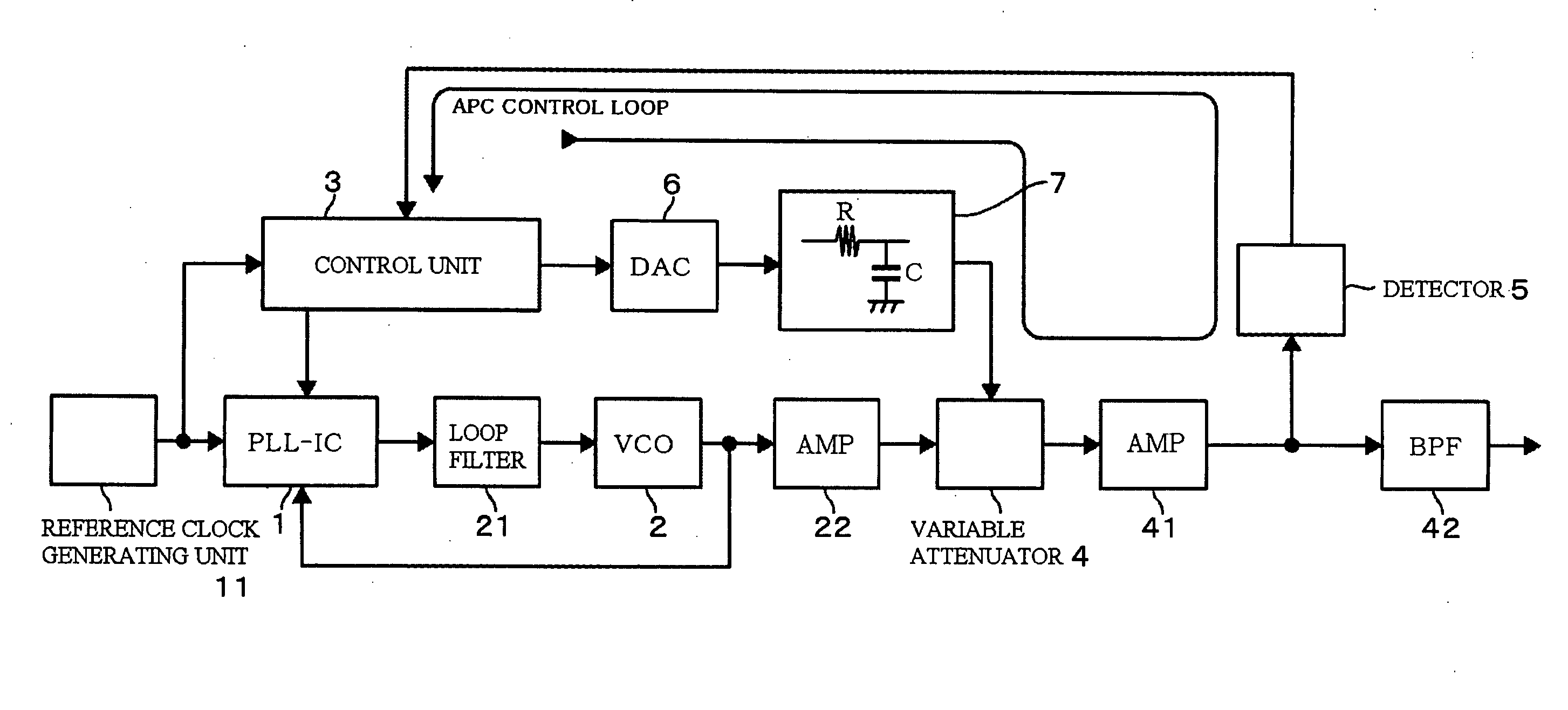
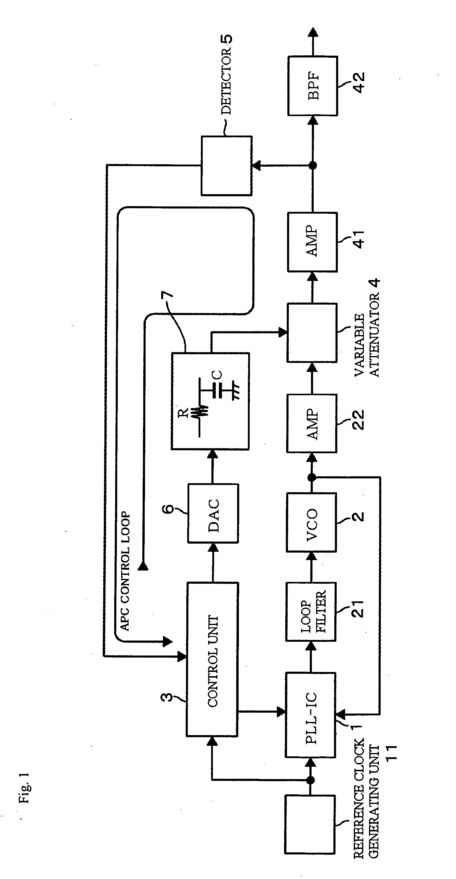
[0036]FIG. 1 is a block diagram showing a first embodiment of a frequency synthesizer according to the present invention. This embodiment is different from FIG. 10 that shows a conventional frequency synthesizer in that (1) a low-pass filter 7 is provided between an output side of the digital / analog converter and the variable attenuator 4, and (2) a function of the control unit 3 is different. First, explanation regarding an example of the PLL integrated circuit unit 1, which was not described in the explanation in FIG. 10, will be made. For example, the PLL integrated circuit unit 1 includes: a frequency dividing part dividing a frequency of an output of the voltage controlled oscillator 2; an A / D converting part provided at a subsequent stage of the frequency dividing part; a part performing quadrature detection of an output of the A / D converting part using a reference clock and extracting a rotation vector K which rotates at a frequency equal to a difference between both frequenc...

second embodiment

[0054]FIG. 8 is a block diagram showing a second embodiment of the frequency synthesizer according to the present invention. This embodiment is different from the first embodiment shown in FIG. 1 in that a comparator 8 is used, instead of the DAC 6 that forms the APC control loop. The target value of detection voltage (target voltage) V1 is input from the control unit 3 into an input end on a positive side of the comparator 8, and the detection voltage V2 from the detector 5 is input into an input end on a negative side of the comparator 8. As the detector 5, one exhibiting the characteristic of monotone increasing is used. The target voltage V1 is a voltage value corresponding to a desired value of an output level of the frequency synthesizer. On an output side of the comparator 8, the low-pass filter 7 is provided, and on an output side of the low-pass filter 7, an integrator 9 being an integration circuit unit is provided. The low-pass filter 7 plays a role to cut a frequency com...


PUM


Abstract

To provide, in a frequency synthesizer including: a variable attenuator provided at a subsequent stage of a voltage controlled oscillator; a detector; and a control unit outputting a control voltage for adjusting an attenuation amount of the variable attenuator via a digital/analog converter in accordance with a detection voltage, a technology with which a spurious due to a change in an output of the digital/analog converter can be suppressed. A low-pass filter is provided between an output side of a digital/analog converter and a variable attenuator to cut a frequency component corresponding to an overshoot generated when an output of the digital/analog converter is changed. Further, a period of time from when a control unit outputs a control voltage to when it reads a signal level detected by a detector is set to a period of time longer than a time constant of the low-pass filter determined by a cut-off frequency of the low-pass filter so that no influence is exerted on an operation of automatically controlling the signal level.

Description

BACKGROUND OF THE INVENTION[0001]1. FIELD OF THE INVENTION[0002]The present invention relates to a technical field in which an output signal level of a frequency synthesizer, for example, is automatically adjusted by a variable attenuator.[0003]2. DESCRIPTION OF THE RELATED ART[0004]Generally, in a high-frequency apparatus, in order to make a signal level (amplitude value) of high-frequency signal constant, an APC (Auto Power Control) is performed in which a variable attenuator is provided in a high-frequency signal path and a control voltage of the variable attenuator is controlled based on a signal level obtained by a detector on an output side (at a subsequent stage) of the variable attenuator.[0005]FIG. 10 is a circuit of a frequency synthesizer in which an APC function is incorporated. 1 denotes a PLL integrated circuit unit (PLL-IC) in which PLL (Phase Locked Loop) circuits are integrated. The PLL integrated circuit unit 1 operates to synchronize, based on a control signal fro...

Claims


Application Information

Patent Timeline
Patent Type & Authority Applications(United States)
IPC IPC(8): H03B21/00H03L7/06
CPCH03G1/0058H03G3/30H03L5/00H03B21/00
Inventor KITAYAMA, YASUODEMURA, HIROYUKIONISHI, NAOKI
Owner NIHON DEMPA KOGYO CO LTD
Why Eureka
Try Eureka