Energy management systems and methods with thermoelectric generators

a technology of energy management system and thermoelectric generator, which is applied in the direction of liquid/fluent solid measurement, process and machine control, instruments, etc., can solve the problems of increasing the amount of waste heat, increasing the efficiency of waste heat, and the operation of existing thermoelectric generators (tegs) is not very efficient or flexible, so as to improve the efficiency and/or operation of primary power sources.

Inactive Publication Date: 2012-05-10
GENTHERM INC
View PDF2 Cites 61 Cited by
  • Summary
  • Abstract
  • Description
  • Claims
  • Application Information

AI Technical Summary

Benefits of technology

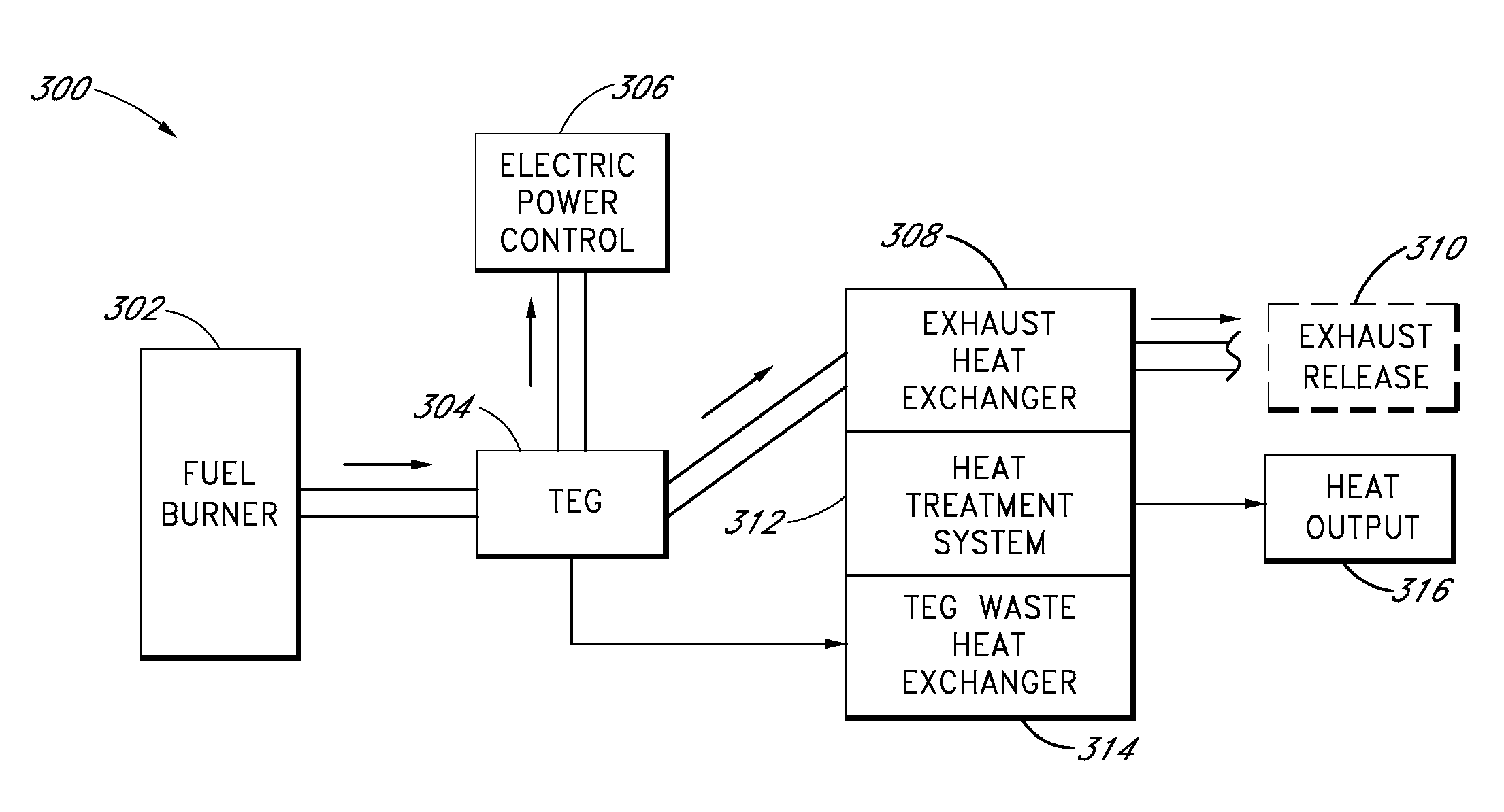
[0011]An energy management system can be configured to use an SSG in one or more modes of operation. For example, in some modes of operation, the system uses the SSG to convert at least a portion of the waste heat generated by a primary power source into electrical energy. In certain modes of operation, the system uses the SSG to convert at least a portion of a primary output of the primary power source into electrical power, where the primary output is thermal energy. In some such modes of operation, the conversion of the primary output into electrical power occurs before, after, and / or simultaneously with another use of the primary output. In some embodiments, the system uses the SSG to generate auxiliary electrical power when the primary power source is at less than full operation or inoperable. In certain embodiments, the system uses the SSG to generate additional electrical power when the primary power source is at substantially at full capacity operation. In some embodiments, the thermal output of the SSG is used to improve the efficiency and / or operation of the primary power source.

Problems solved by technology

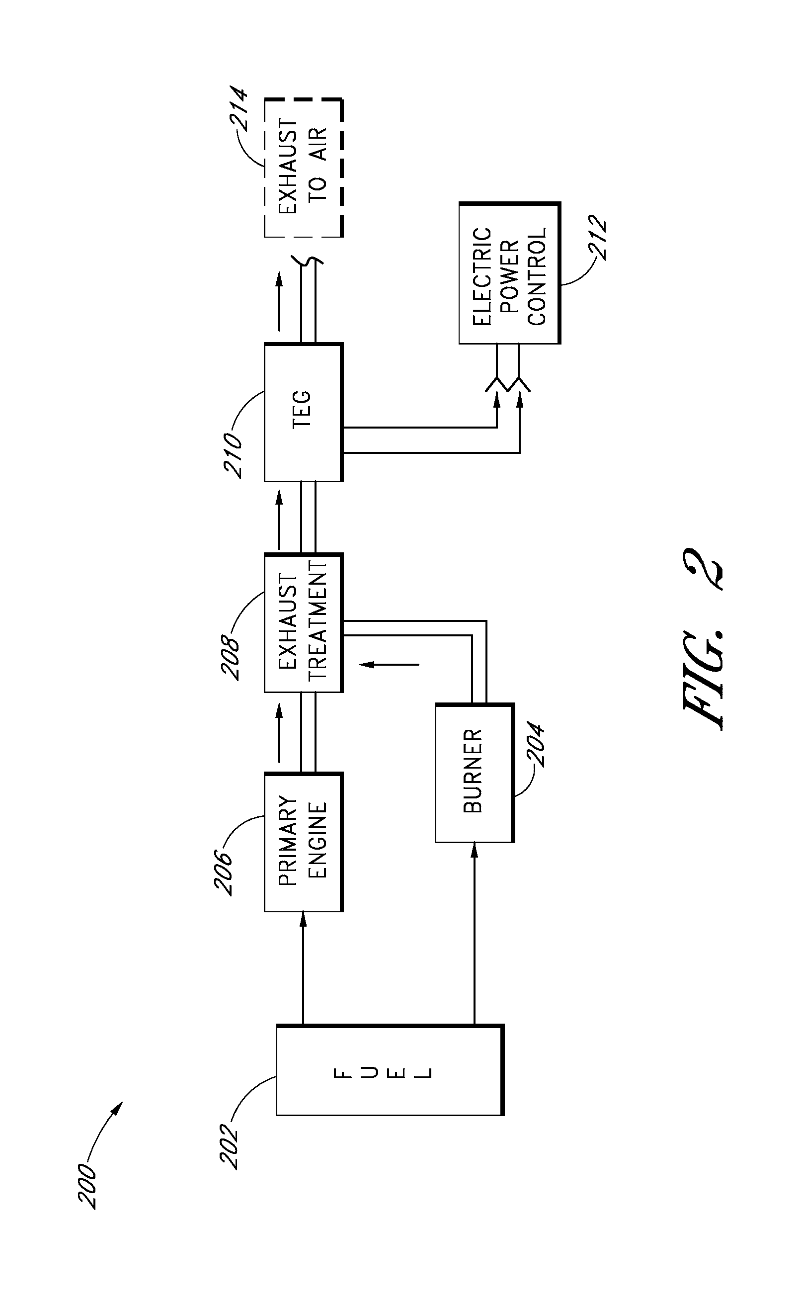
In motor vehicles, additional processing of exhaust after its removal from the power plant, including chemical reactions and emissions reduction techniques, can heat the exhaust and increase the amount of waste heat.
At least some existing thermoelectric generators (TEGs) are not very efficient or flexible in their operation.

Method used


Image

  • Energy management systems and methods with thermoelectric generators
  • Energy management systems and methods with thermoelectric generators
  • Energy management systems and methods with thermoelectric generators

Examples


Embodiment Construction

[0029]Although certain preferred embodiments and examples are disclosed herein, inventive subject matter extends beyond the specifically disclosed embodiments to other alternative embodiments and / or uses of the inventions, and to modifications and equivalents thereof. Thus, the scope of the inventions herein disclosed is not limited by any of the particular embodiments described below. For example, while some energy management system and method embodiments are described with reference to a TEG or TPG, it is understood that any SSG can be used in addition to or in place of a TEG or TPG. As another example, in any method or process disclosed herein, the acts or operations of the method or process may be performed in any suitable sequence and are not necessarily limited to any particular disclosed sequence.

[0030]For purposes of contrasting various embodiments with the prior art, certain aspects and advantages of these embodiments are described. Not necessarily all such aspects or advan...


PUM


Abstract

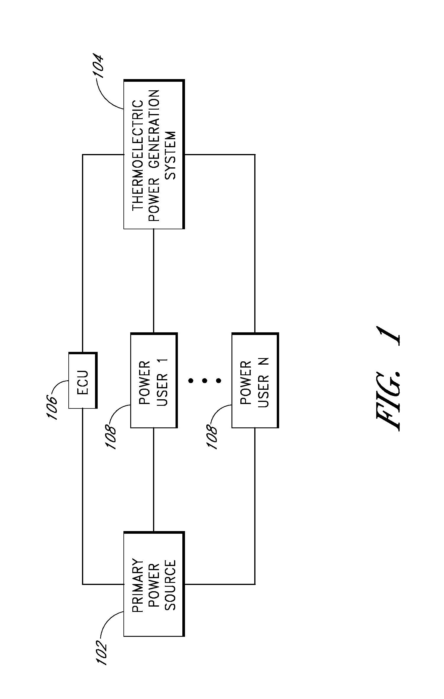
In some embodiments, an integrated power generation system includes a primary power source supplying power to a primary power user, a thermoelectric power generator system thermally coupled to a heat source, and an electronic controller unit. In certain embodiments, an electronic controller unit monitors the power output of the primary power source and operatively connects the thermoelectric power generating system to the primary power user when one or more power usage factors occurs. One power usage factor that can occur is the power output of the primary power source falling below a threshold power level.

Description

RELATED APPLICATION[0001]This application claims the benefit under 35 U.S.C. §119(e) of U.S. Provisional Application No. 61 / 410,773, filed Nov. 5, 2010, titled INTEGRATED WASTE HEAT RECOVERY AND POWER GENERATION, the entire contents of which are incorporated by reference herein and made part of this specification.BACKGROUND[0002]1. Field[0003]This disclosure generally relates to energy management systems that incorporate one or more thermoelectric devices.[0004]2. Description of Related Art[0005]Power equipment commonly produces waste heat in addition to a desired output. For example, a motor vehicle typically converts fuel energy into mechanical energy and waste heat. Commercial power plants typically generate electrical power and waste heat from coal, natural gas, nuclear fission, wind power, solar power, geothermal power, or other power sources. Heating, ventilation, and air conditioning systems and water heaters typically generate waste heat in addition to conditioned fluid.[000...

Claims


Application Information

Patent Timeline
Patent Type & Authority Applications(United States)
IPC IPC(8): H01L35/30G06F1/26
CPCH01L35/30H01L35/00H10N10/00H10N10/13
Inventor BELL, LON E.CRANE, DOUGLAS T.KOSSAKOVSKI, DMITRIPARK, DARRELLLAGRANDEUR, JOHN
Owner GENTHERM INC
Why Eureka
Try Eureka