Vacuum cleaner and method for controlling an electric motor

Active Publication Date: 2012-05-10
AB ELECTROLUX
View PDF9 Cites 16 Cited by
  • Summary
  • Abstract
  • Description
  • Claims
  • Application Information

AI Technical Summary

Benefits of technology

[0017]The invention is advantageous e.g. since a vacuum cleaner according to the invention can be controlled more accurately than prior art vacuum cleaners with respect to motor power towards a target motor power value.
[0018]Compared to a prior art vacuum cleaner designed to have sufficient suction power for conditions where the airflow is not reduced, a vacuum cleaner of the invention can be designed to have sufficient suction power in conditions where the airflow is not reduced, but at the same time have the same or similar motor power, and hence the same or similar suction power, for conditions where the airflow is reduced, whereas the prior art vacuum cleaner would have a lower or even much lower motor power, and hence suction power, for conditions where the airflow is reduced. Hence, in this scenario, a vacuum cleaner of the invention will have sufficient motor power both in conditions where the airflow is reduced and in conditions where the airflow is not reduced, whereas the prior art vacuum cleaner would hav

Problems solved by technology

Battery products have a general disadvantage compared to corded AC products since battery capacity is expensive and heavy.
In a battery powered vacuum cleaner including an electric motor, a decrease of battery power during the discharge cycle of the battery will result in a decrease of the suction power of the vacuum cleaner during the discharge cycle of the battery.
A problem with the prior art methods of controlling battery powered electric motors in vacuum cleaners is that the motor power and hence the suct

Method used


Image

  • Vacuum cleaner and method for controlling an electric motor
  • Vacuum cleaner and method for controlling an electric motor
  • Vacuum cleaner and method for controlling an electric motor

Examples


first embodiment

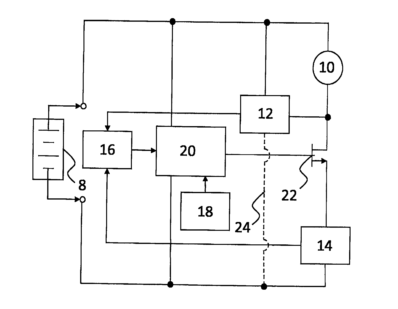
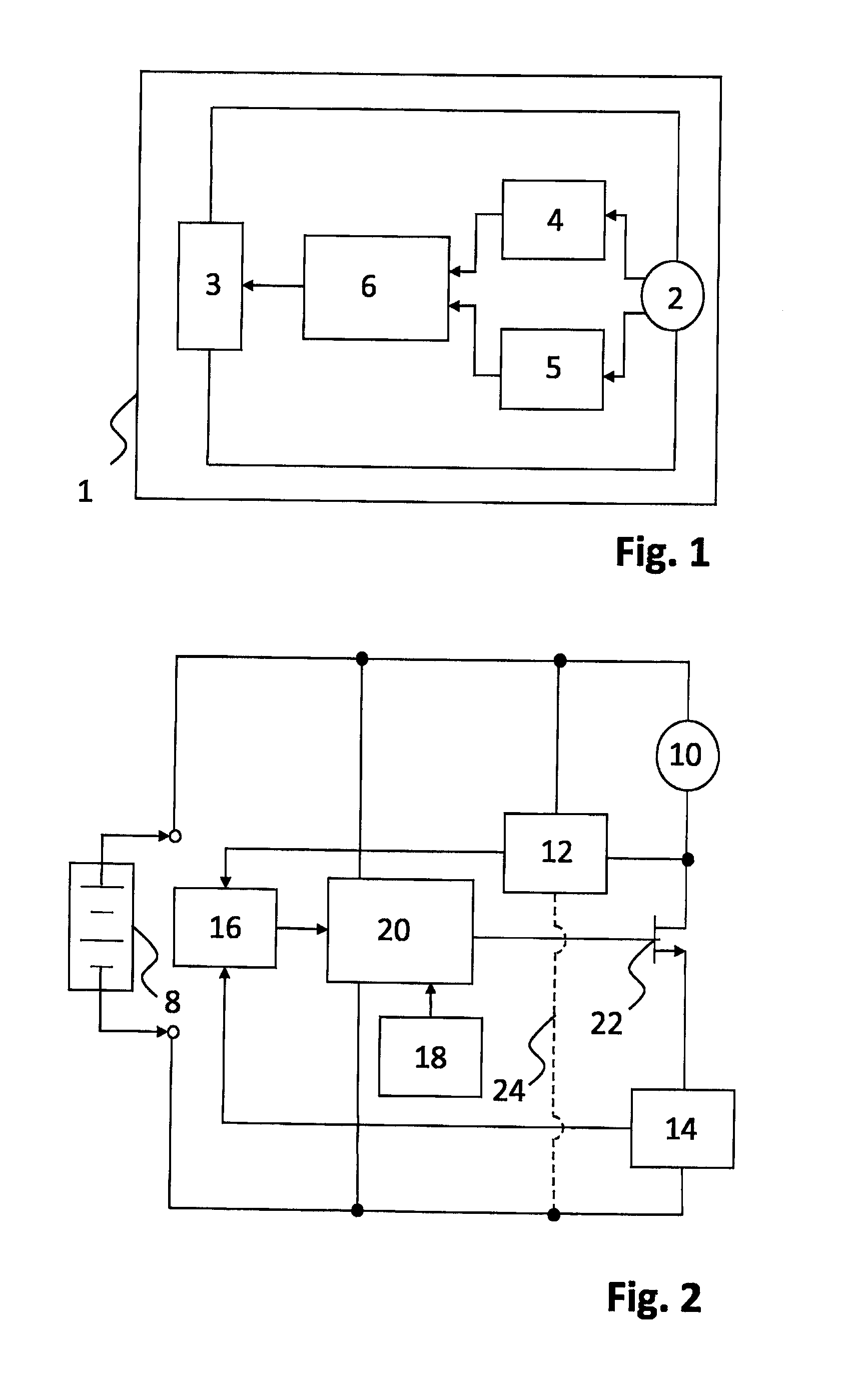
[0041]a vacuum cleaner according to the invention is shown in the schematic block diagram of FIG. 2. A DC power supply 8, e.g. a battery, powers an electric motor 10.

[0042]In the first embodiment the electric motor 10 is connected to a fan (not shown) which creates an airflow through the vacuum cleaner. A voltage measuring means 12 and a current measuring means 14 are provided. The voltage measuring means 12 measures a motor voltage applied over the electric motor 10 and the current measuring means 14 measures the motor current flowing through the electric motor 10. The voltage measuring means 12 and the current measuring means 14 provide the measured motor voltage and the measured motor current, respectively, to an actual motor power calculation means 16. The actual power calculation means 16 calculates the actual motor power value and provides the actual motor power value to a control means 20. Furthermore, a target motor power means 18 provides a target motor power value to the c...

second embodiment

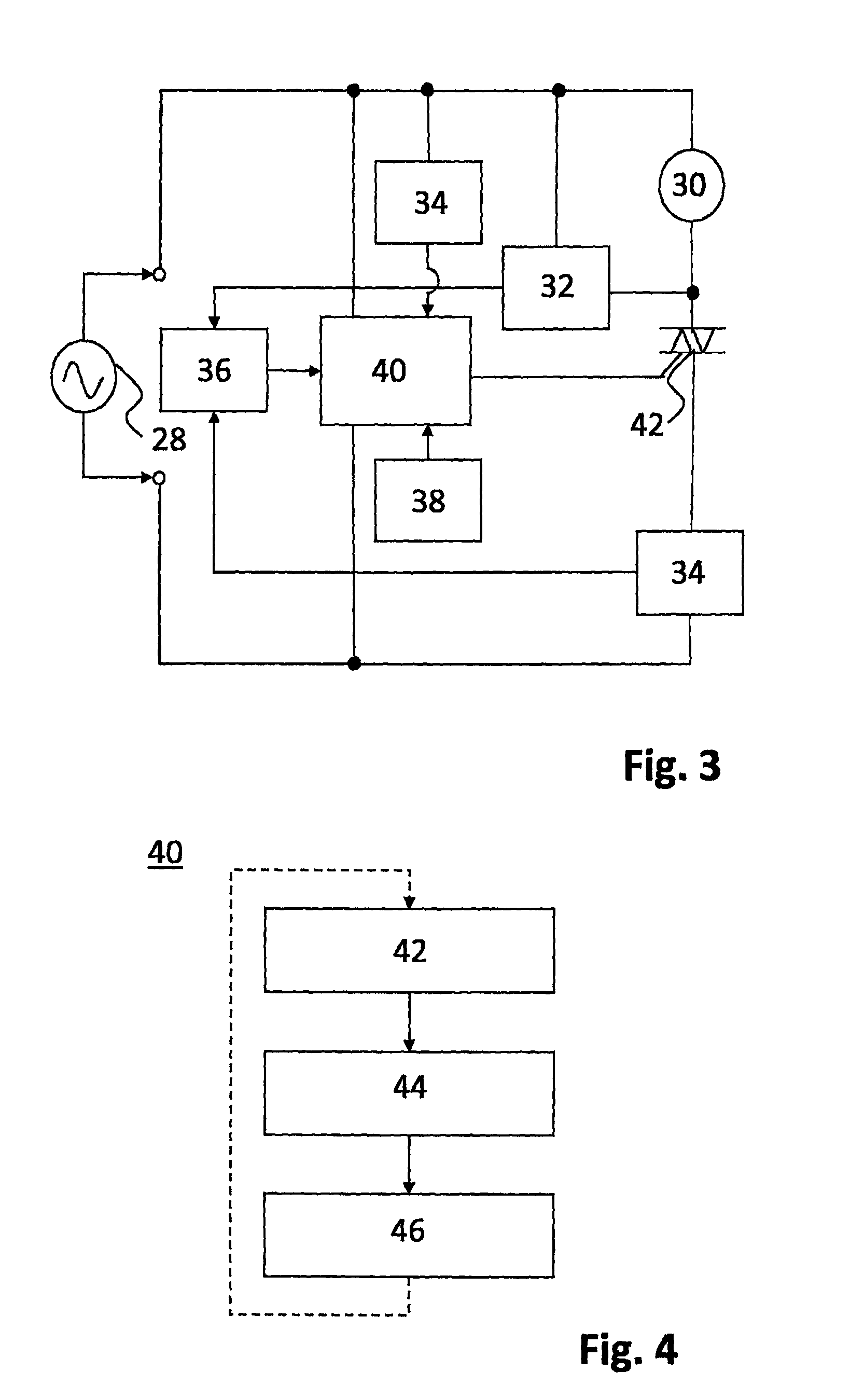
[0057]The control means 40 of the second embodiment includes a time delay means for generating a time delay and a processor means for determining the time delay based on the actual motor power value and the target motor power value. The control means 40 is further arranged to provide a control signal after the determined time delay in relation to a zero-cross point as indicated by the zero-cross signal.

[0058]The second embodiment comprises a switching means in the form of a bi-directional thyristor 42 or similar connected between the motor 30 and the control means 40.

[0059]The control means 40 determines a time delay signal based on the actual motor power level, the target motor power level and the zero-cross detection signal received from the zero-cross detection means. The time signal is provided by the time delay means to a gate terminal of the bi-directional thyristor 42.

[0060]When a power voltage having a sinus waveform from the AC power supply 28 is applied to the control mean...


PUM


Abstract

A vacuum cleaner and a method for controlling the motor power of a vacuum cleaner are disclosed. The vacuum cleaner comprises an electric motor and an electric power supply for providing electric power to the electric motor. Furthermore, a voltage measuring means for measuring a motor voltage over the electric motor and a current measuring means for measuring a motor current flowing through the electric motor are provided. The vacuum cleaner further comprises a control means for controlling, based on the measured voltage and the measured current, the electric power provided to the electric motor from the electric power supply towards a target motor power value.

Description

FIELD OF THE INVENTION [0001]The invention relates to a vacuum cleaner including an electric motor and control means for controlling the electric motor and a method for controlling an electric motor in a vacuum cleaner.BACKGROUND OF THE INVENTION[0002]Battery products have a general disadvantage compared to corded AC products since battery capacity is expensive and heavy. Furthermore, battery voltage is reduced during a discharge cycle of a battery. In a battery powered vacuum cleaner including an electric motor, a decrease of battery power during the discharge cycle of the battery will result in a decrease of the suction power of the vacuum cleaner during the discharge cycle of the battery. Generally, the maximum inlet power of a fan unit of a vacuum cleaner powered by battery will decrease with half or more during the discharge cycle of the battery. Also, ageing of the battery will impact the power output such that the initial and highest power available can be reduced with more t...

Claims


Application Information

Patent Timeline
IPC IPC(8): H02P7/29H02P23/00H02P7/00
CPCA47L9/2831A47L9/2842A47L9/2889A47L9/2878H02P7/295Y02B40/82H02P2205/03H02P7/29Y02B40/00A47L9/28H02P25/08H02P27/04
Inventor DANESTAD, ULRIKPERSSON, MICHAEL
Owner AB ELECTROLUX
Why Eureka
Try Eureka