Secondary battery temperature-increasing control apparatus and vehicle including the same, and secondary battery temperature-increasing control method

a control apparatus and battery technology, applied in battery/fuel cell control arrangement, electric devices, instruments, etc., can solve the problem of significantly affecting the amount of heat generated in the battery, and achieve the effect of efficiently generating a target amoun

Inactive Publication Date: 2012-05-10
TOYOTA JIDOSHA KK
View PDF3 Cites 33 Cited by
  • Summary
  • Abstract
  • Description
  • Claims
  • Application Information

AI Technical Summary

Benefits of technology

[0009]The invention provides a secondary battery temperature-increasing control apparatus for efficiently generating a target amount of heat within the range, in which the voltage of a secondary battery does not exceed the upper limit voltage of the secondary battery nor fall below the lower limit voltage thereof, and provides a vehicle including such a secondary battery temperature-increasing control apparatus.
[0010]The invention also provides a secondary battery temperature-increasing control method of efficiently generating a target amount of heat within the range, in which the voltage of a secondary battery does not exceed the upper limit voltage of the secondary battery nor fall below the lower limit voltage thereof.
[0014]In the above first aspect, a configuration may be employed, in which the ripple generating section includes a chopper-type booster configured to be capable of boosting an output voltage of the booster to or above the voltage of the secondary battery, the feed back control section increases a boost ratio of the booster when the ripple current is less than the target, and the feed back control section reduces the boost ratio of the booster when the ripple current is greater than the target.
[0019]In the third aspect of the invention, a configuration may be employed, in which the ripple generating section includes a chopper-type booster configured to be capable of boosting an output voltage of the booster to or above the voltage of the secondary battery, and the secondary battery temperature-increasing control method further includes: when the ripple current is less than the target, increasing a boost ratio of the booster; and when the ripple current is greater than the target, reducing the boost ratio of the booster.
[0022]Thus, according to the invention, the target amount of heat is efficiently generated within the range, in which the voltage of the secondary battery does not exceed the upper limit voltage nor fall below the lower limit voltage.

Problems solved by technology

Thus, the amount of heat generated in the battery is significantly affected by the unevenness of the inductance L and / or the characteristics of the battery.

Method used


Image

  • Secondary battery temperature-increasing control apparatus and vehicle including the same, and secondary battery temperature-increasing control method
  • Secondary battery temperature-increasing control apparatus and vehicle including the same, and secondary battery temperature-increasing control method
  • Secondary battery temperature-increasing control apparatus and vehicle including the same, and secondary battery temperature-increasing control method

Examples


first embodiment

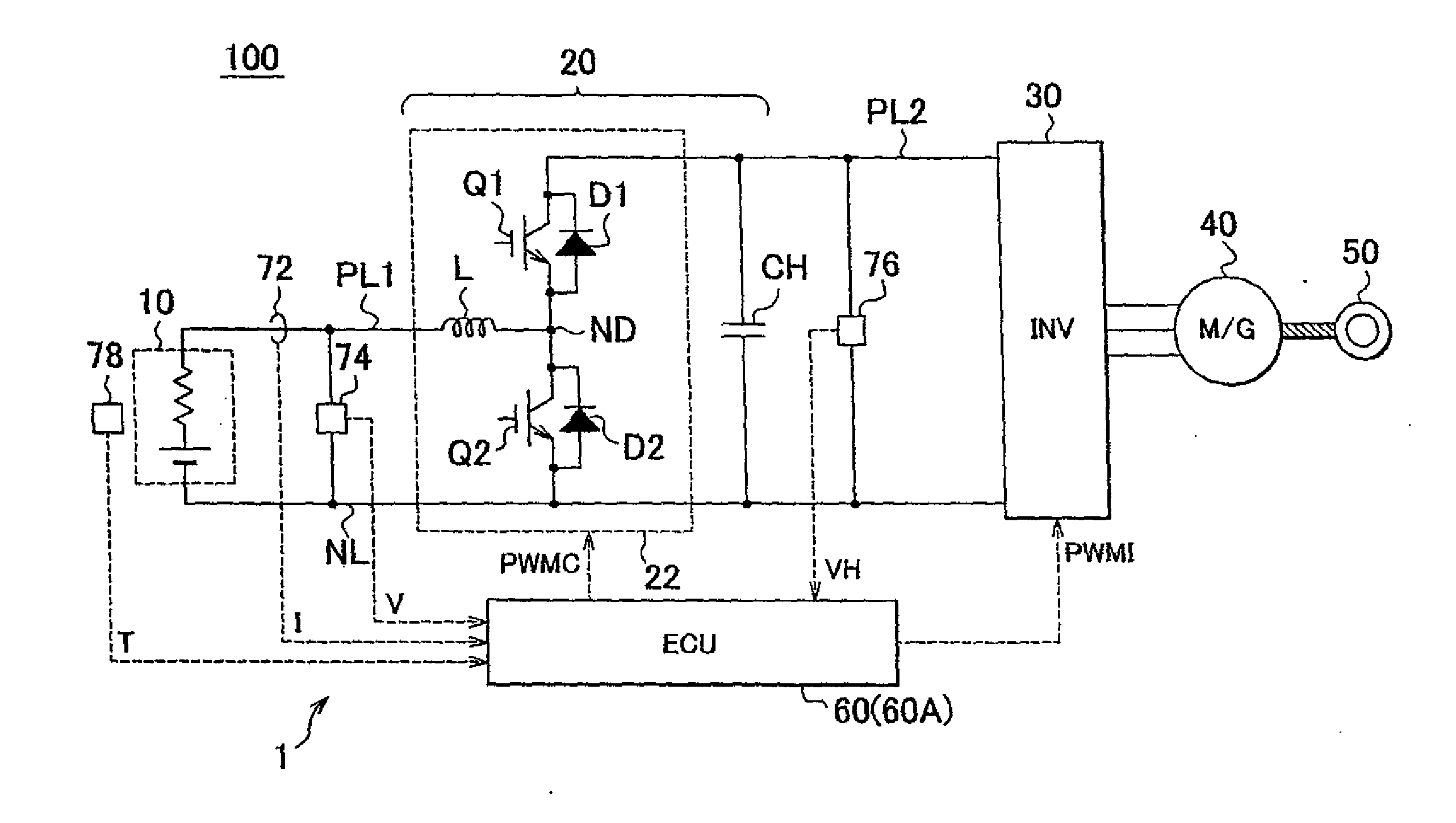
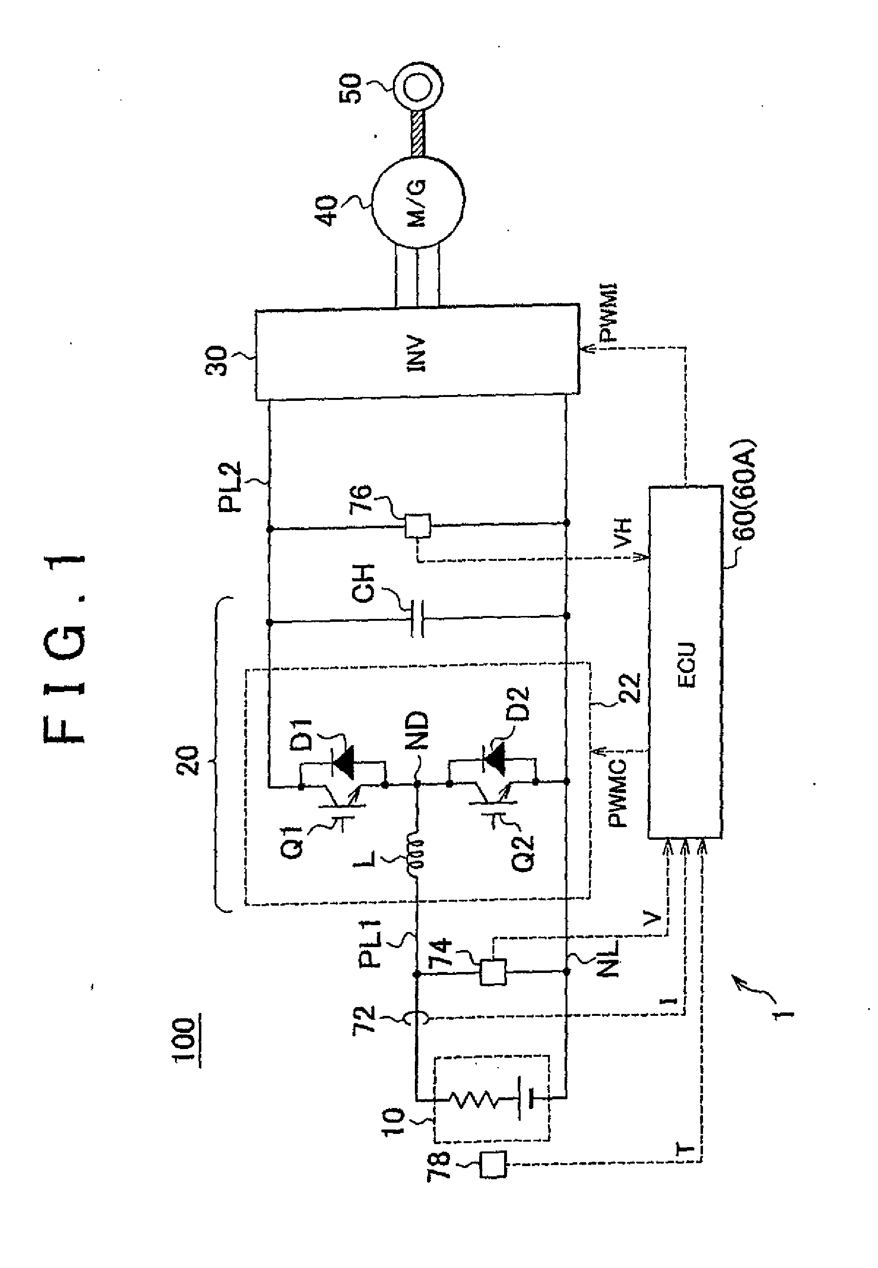
[0037]FIG. 1 is a block diagram of the whole of an electric vehicle that is given as an application example of a secondary battery temperature-increasing control apparatus 1 according to a first embodiment of the invention. Referring to FIG. 1, the electric vehicle 100 includes the secondary battery 10, a boost converter 22, a capacitor CH, an inverter 30, a motor generator 40, and a driving wheel 50. The electric vehicle 100 further includes an electronic control unit (ECU) 60, an electric current sensor 72, voltage sensors 74 and 76, and a temperature sensor 78.

[0038]The secondary battery 10 is a rechargeable battery, typified by a lithium ion battery or a nickel-hydrogen battery. A positive terminal and a negative terminal of the secondary battery 10 are connected to a positive line PL1 and a negative line NL, respectively.

[0039]The boost converter 22 includes power semiconductor switching devices (hereinafter also referred to merely as “the switching devices”) Q1 and Q2, diodes ...

second embodiment

[0095]In the above first embodiment, the ripple current is controlled to be brought to the target by changing the carrier frequency (ripple frequency) of the boost converter 22. In a second embodiment, the ripple current is controlled by adjusting the boost ratio of the boost converter 22 (that is, by adjusting the switching duty factors of the switching devices Q1 and Q2).

[0096]An overall configuration of an electric vehicle, in which a secondary battery temperature-increasing control apparatus according to the second embodiment is used, is the same as that of the electric vehicle 100 shown in FIG. 1.

[0097]FIG. 11 is a functional block diagram of part of the ECU 60A of the second embodiment, the part relating to the control of the boost converter 22. Referring to FIG. 11, the ECU 60A includes a duty command generating section 114A, a ripple temperature increase FB control section 118A, and a carrier generating section 122A, instead of the duty command generating section 114, the ri...


PUM

PropertyMeasurementUnit
power factoraaaaaaaaaa
frequencyaaaaaaaaaa
temperatureaaaaaaaaaa

Abstract

An ECU determines whether the ripple current is within a target range (S50). When it is determined that the ripple current is not within the target range (NO in S50), the ECU determines whether the ripple current is greater than or less than the target range (S80). When it is determined that the ripple current is less than the target range (NO in S80), the ECU reduces the carrier frequency of the boost converter that is a component of the ripple generating section (S90). On the other hand, when it is determined that the ripple current is greater than the target range (YES in S80), the ECU increases the carrier frequency of the boost converter (S100).

Description

BACKGROUND OF THE INVENTION[0001]1. Field of the Invention[0002]The invention relates to a secondary battery temperature-increasing control apparatus and a vehicle including the same and to a secondary battery temperature-increasing control method. In particular, the invention relates to a technology for performing temperature increasing control to increase the temperature of the secondary battery with the use of the heat generation caused by the internal resistance of the secondary battery.[0003]2. Description of the Related Art[0004]In general, in secondary batteries, typified by lithium-ion batteries and nickel-hydrogen batteries, charging and discharging characteristics are degraded as the temperature decreases. When the temperature of the battery is low, it is required to quickly increase the temperature of the battery.[0005]Japanese Patent Application Publication No. H11-329516 (JP-A-11-329516) describes an apparatus for increasing the temperature of a battery. In the temperat...

Claims


Application Information

Patent Timeline
Patent Type & Authority Applications(United States)
IPC IPC(8): H02J7/00H01M10/48B60L3/00G01R31/36H01M10/60H01M10/615H01M10/625H01M10/633H01M10/6571H02J7/10
CPCB60L3/0046B60L3/0053B60L11/1872B60L11/1875Y02T90/34Y02T10/7005Y02T10/7011Y02T10/705Y02T10/7225B60L2210/14B60L58/12B60L58/25B60L58/27B60L58/34B60L58/40Y02E60/10Y02T10/70Y02T10/72Y02T90/40H01M10/625H01M10/637
Inventor NISHI, YUJITAKAHASHI, HIDENORITAZAWA, MASATOSHI
Owner TOYOTA JIDOSHA KK
Why Eureka
Try Eureka