Rectifier circuit

Inactive Publication Date: 2012-05-10
INVENTEC CORP
View PDF7 Cites 14 Cited by
  • Summary
  • Abstract
  • Description
  • Claims
  • Application Information

AI Technical Summary

Benefits of technology

[0018]Therefore, when being adopted, the rectifier circuit of the present invention does not need an additional capacitor element, and can not only improve a light

Problems solved by technology

However, a defect of this power source lies in that, when the power source stays in a high-frequency working state, the output ripple voltage is relatively large.
Among the existing switching power sources, a synchronous rectification BUCK switching power source is most widely used, which has the problem of a large ripple current caused by the factors of on/off of the MOSFET, electricity storage and discharge of an inductive element and charge/discharge of a capacitor, and the problem inevitably results in a large noise occurring at an output e

Method used


Image

  • Rectifier circuit
  • Rectifier circuit
  • Rectifier circuit

Examples


Embodiment Construction

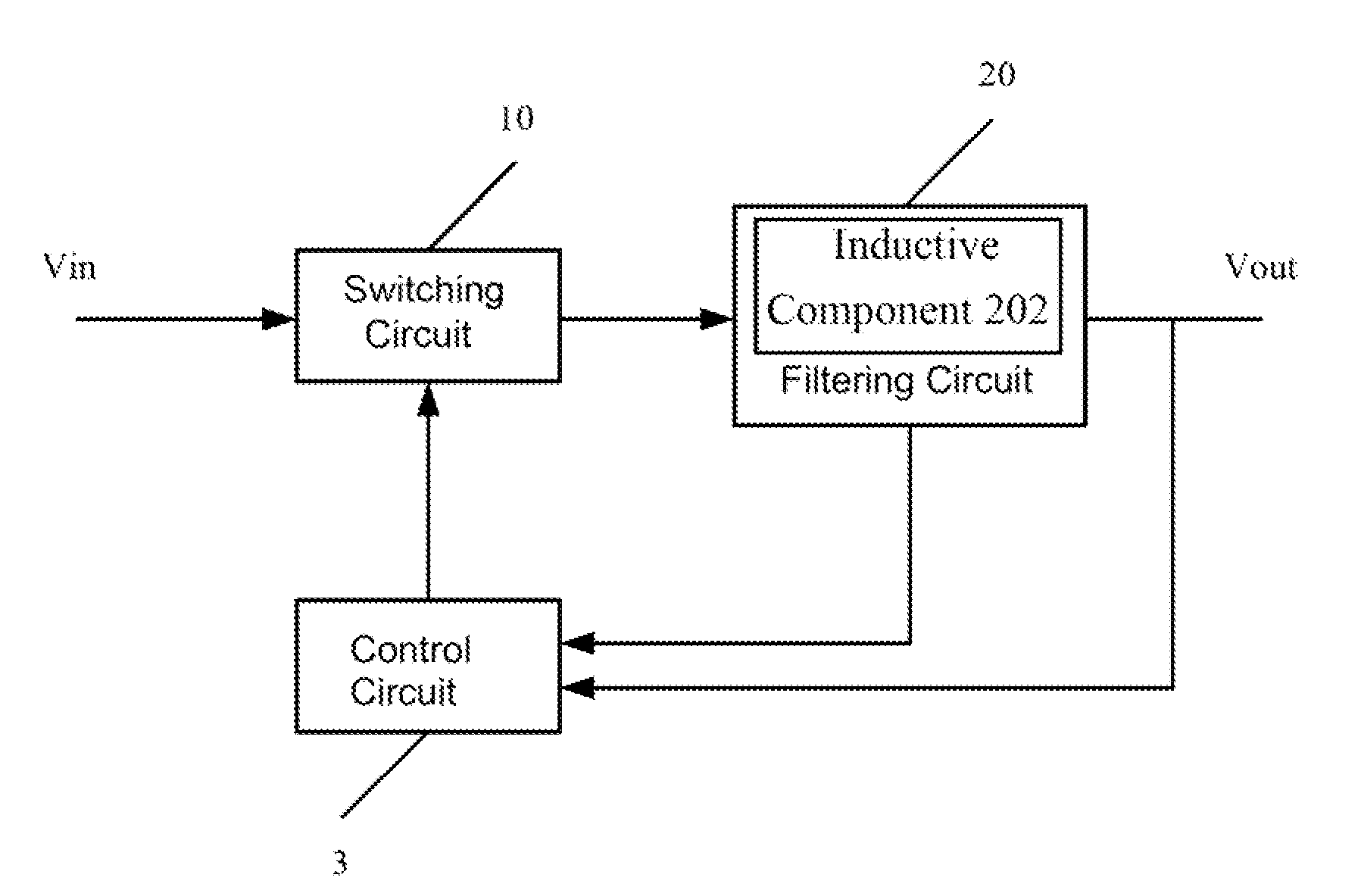
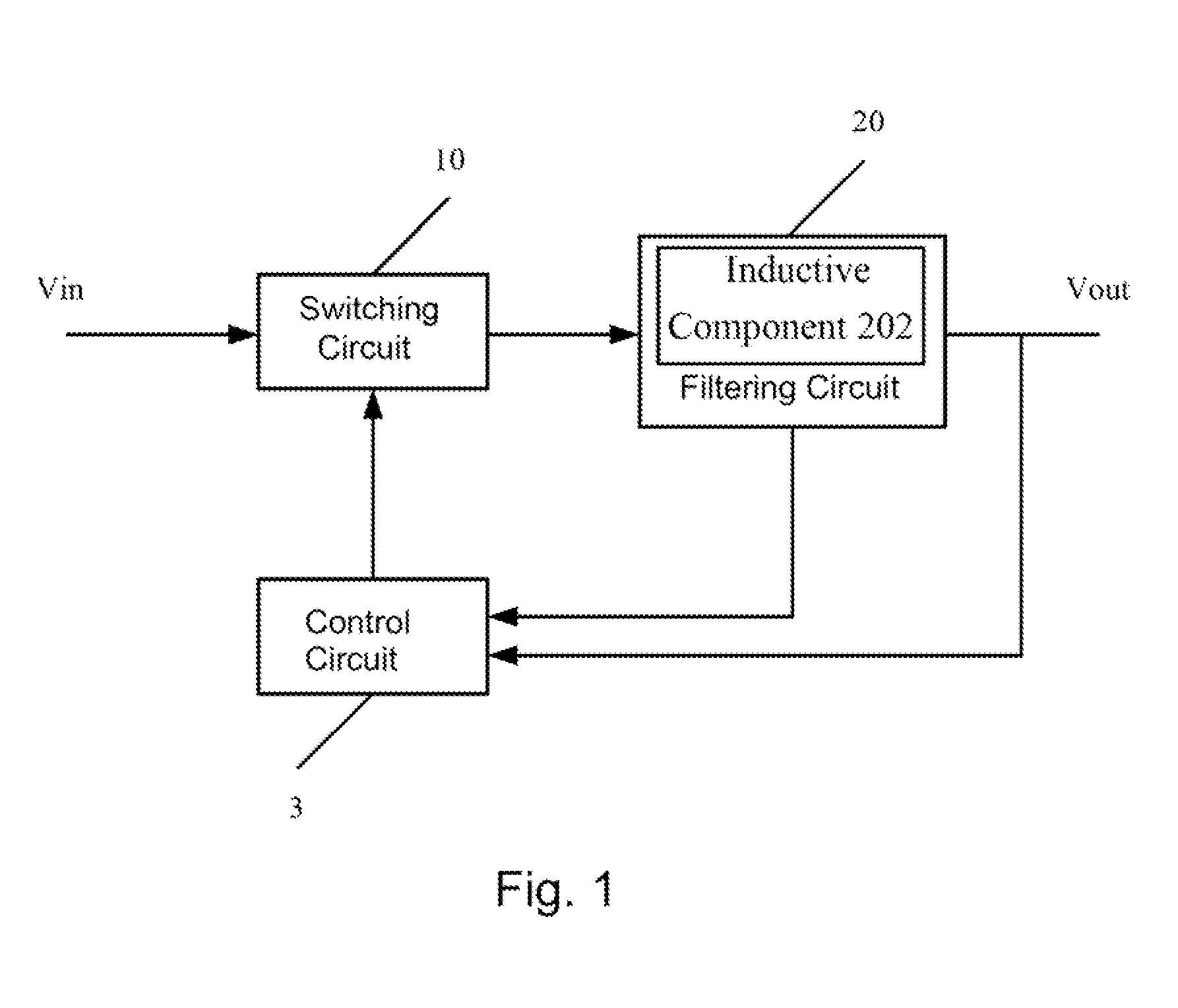
[0025]FIG. 1 is a block diagram illustrating the connections of respective functional modules in a rectifier circuit according to a preferred embodiment of the present invention. Referring to FIG. 1, the rectifier circuit includes a switching circuit 10, a filtering circuit 20 and a control circuit 3. The switching circuit 10 has an input end, an output end and a control end, wherein the input end is used for receiving an input voltage Vin, and the output end is electrically connected to the filtering circuit 20, and the control end is electrically connected to the control circuit 3. The switching circuit 10 is controlled by a pulse width modulation signal outputted by the control circuit 3.

[0026]The control circuit 3 is electrically connected between the control end of the switching circuit 10 and an output terminal Vout of the rectifier circuit for controlling the pulse width modulation signal of the switching circuit, thereby regulating the output voltage. Particularly, when a lo...


PUM


Abstract

A rectifier circuit includes: a switching circuit having an input end, an output terminal and a control end, wherein the input end of the switching circuit receives an input voltage; a control circuit electrically connected to the control end of the switching circuit, wherein, when a load current is smaller than a reference current, the rectifier circuit is situated at a light-load state and the control circuit reduces a switching frequency of the switching circuit; and a filtering circuit which is electrically connected between the output end of the switching circuit and an output terminal of the rectifier circuit, and includes at least one inductive component of which a current is formed by superposition of the load current and a ripple current, wherein, when the load current is smaller than the reference current, an inductance of the inductive component increases with the decrease of the load current.

Description

RELATED APPLICATIONS[0001]This application claims priority to China Application Serial Number 201010539649.2, filed Nov. 8, 2010, which is herein incorporated by reference.BACKGROUND[0002]1. Field of Invention[0003]The present invention relates to a rectifier circuit. More particularly, the present invention relates to a rectifier circuit capable of improving a light-load efficiency and decreasing an amplitude of a ripple current.[0004]2. Description of Related Art[0005]Currently, all kinds of electronic products are designed with increasingly complicated functions, and various power source technologies are also developed at a high speed to meet the working requirements of the electronic products. At present, most of the electronic products adopt a switching power source including an AC / DC convertor, a DC / DC convertor and so on, and compared with a conventional linear power source, the switching power source has a distinctive advantage of high conversion efficiency, which may genera...

Claims


Application Information

Patent Timeline
IPC IPC(8): G05F1/10
CPCH02M1/143Y02B70/1466H02M3/1588Y02B70/10
Inventor XIA, CHUN-HUAPENG, TZE-HSIN
Owner INVENTEC CORP
Why Eureka
Try Eureka