Light guide plate and backlight module

Active Publication Date: 2012-05-10
TCL CHINA STAR OPTOELECTRONICS TECH CO LTD
View PDF2 Cites 3 Cited by
  • Summary
  • Abstract
  • Description
  • Claims
  • Application Information

AI Technical Summary

Benefits of technology

[0027]The benefits of the present invention is: the fluorescent powder is not coated in the interior of the LEDs of the present invention and therefore, the fluorescent powder is not closing to the heat source to prevent the issues of color shift and the luminous efficiency degradation due to the fluorescent powder accelerated ageing; again, because the optical construction of the light guide plate is the primary factor that light e

Problems solved by technology

Because the liquid crystal itself of the LCD panel does not provide the characteristics of luminescence, a light source device, such as a backlight module is needed for the LCD panel for achieving the display effect.
As aforementioned, the coating of the fluorescent powder in prior art has drawbacks below: First, the LED generates lots of heat in the luminous process.
The heat accumulation leads to the fluorescent powder

Method used


Image

  • Light guide plate and backlight module
  • Light guide plate and backlight module
  • Light guide plate and backlight module

Examples


first embodiment

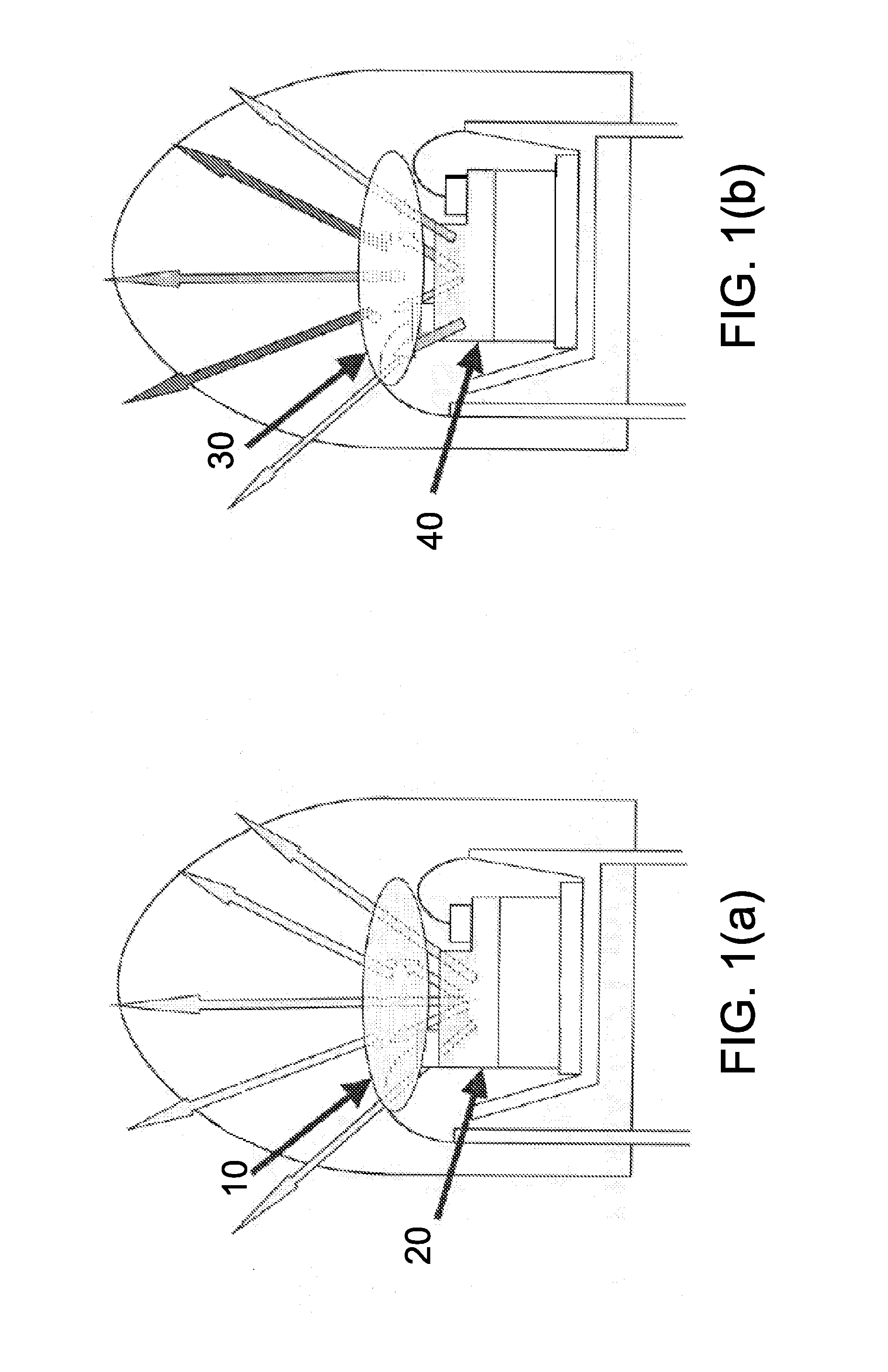
[0046]Shown in FIG. 5 is a diagram of a solution that the composition of the screen dots made by mixing fluorescent powder and ink according to the present invention, i.e. the aforementioned solution A. The side light type LED backlight module in FIG. 5 comprises LEDs 310, a light guide plate 320 and screen dots 330. The composition of the screen dots 330 can be yellow fluorescent powder and ink having diffusion particles; or yellow fluorescent powder, red fluorescent powder and ink having diffusion particles; or green fluorescent powder, red fluorescent powder and ink having diffusion particles.

[0047]In this embodiment that the ink and the fluorescent powder are mixed, as the fluorescent powder and the ink having diffusion particles are mixed to form the screen dots 330, the sizes of the screen dots 330 do not have specific requirements and can be designed according to the real demands. In this embodiment, the diameters of the screen dots 330 can be 0.2˜0.4 mm. Specifically, the sm...

second embodiment

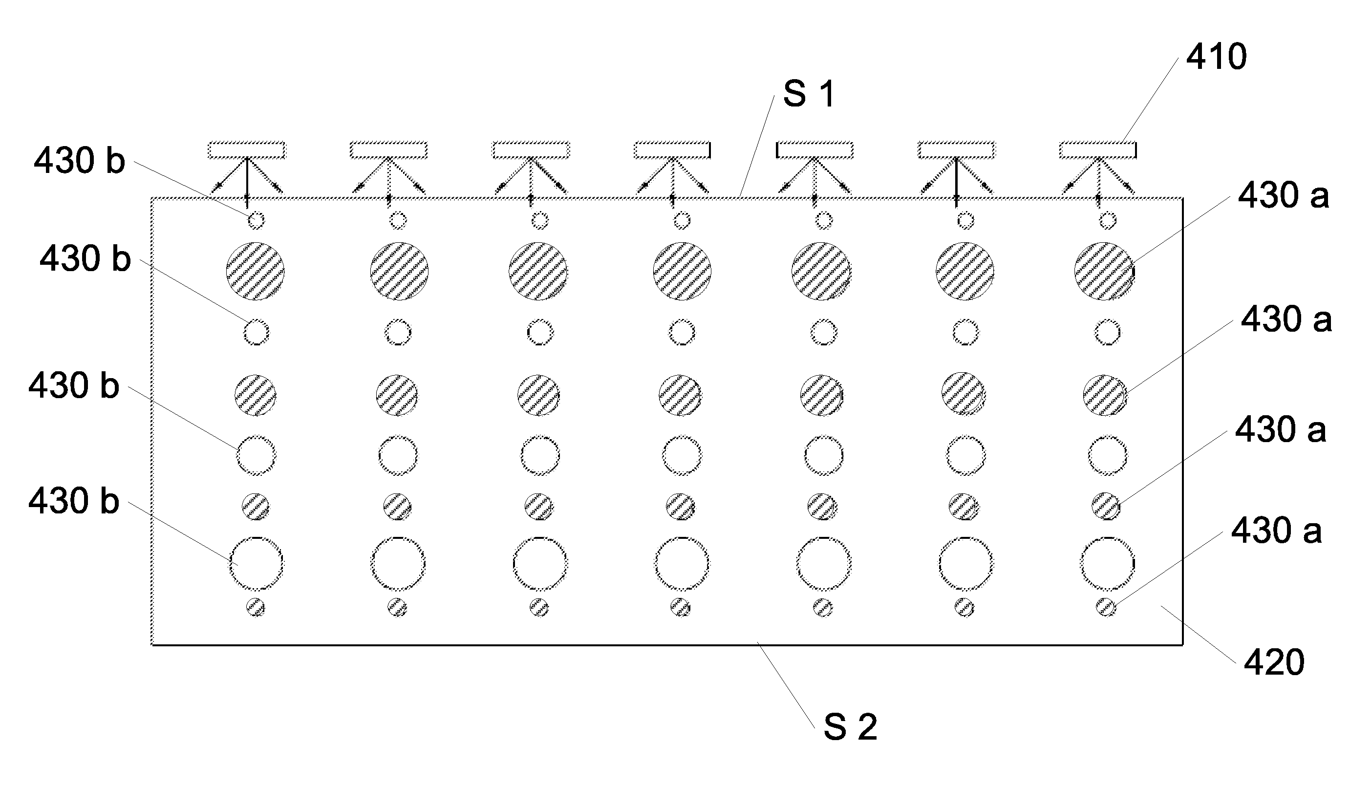
[0049]Shown in FIG. 6 is a diagram of ink screen dots and fluorescent powder screen dots arranged alternately according to the present invention, i.e. the aforementioned solution C. The side light type LED backlight module in FIG. 6 comprises LEDs 410, a light guide plate 420, fluorescent powder screen dots 430a and ink screen dots 430b. In this embodiment, the fluorescent powder screen dots 430a and the ink screen dots 430b having diffusion particles are arranged alternately line by line. In another word, a fluorescent powder screen dot line consisting of the fluorescent powder screen dots 430a and an ink screen dot line consisting of the ink screen dots 430b are arranged alternately. However, the arrangement is not limited thereto in real situations. The composition of the fluorescent powder screen dots 430a can be a mixture of red fluorescent powder and green fluorescent powder; or a mixture of yellow fluorescent powder and red fluorescent powder.

[0050]For the guarantee of unifor...

third embodiment

[0052]Shown in FIG. 7 is a diagram of two-layer screen dots according to the present invention, i.e. the aforementioned solution D. The side light type LED backlight module in FIG. 7 comprises a light guide plate 520, fluorescent powder screen dots 530a and ink screen dots 530b. These screen dots are in double layers. The fluorescent powder screen dots 530a coated by the fluorescent powder are positioned in the upper layer. The ink screen dots 530b coated by the diffusion particles are positioned in the lower layer. The fluorescent powder screen dots comprise a mixture of red fluorescent powder, green fluorescent powder and blue fluorescent powder.

[0053]Thus, the present invention separates the LEDs and the fluorescent powder with each other. The fluorescent powder does not have to be coated in the interior of the LEDs. Therefore, it can be prevented that the LDE color change due to the fluorescent powder accelerated ageing caused by the LED generating heat and the luminous efficien...


PUM


Abstract

The present invention provides a light guide plate and a backlight module, wherein the light guide plate comprises a bottom surface, a light incident surface and a light-emitting surface. The light-emitting surface and the bottom surface are positioned oppositely. The bottom surface comprises a plurality of screen dots. The screen dots comprise fluorescent powder and are selectively added with diffusion particles. The present invention prevents the phenomenon of color shift and the luminous efficiency degradation due to the fluorescent powder accelerated ageing because of closing to the LED chip.

Description

BACKGROUND OF THE INVENTION[0001]1. Field of the Invention[0002]The present invention generally relates to a LCD skill technology, and more particularly to a light guide plate and a backlight module utilizing the light guide plate.[0003]2. Description of Prior Art[0004]Because the liquid crystal itself of the LCD panel does not provide the characteristics of luminescence, a light source device, such as a backlight module is needed for the LCD panel for achieving the display effect. The function of the backlight module is to provide a surface light source fully brighten and uniformly distributed for the LCD panel.[0005]In prior arts, the backlight module comprises a light source, a light guide plate and some other necessary portions. The function of the light guide plate is to guide the propagating direction of the light to allow the light uniformly emitted through the light-emitting surface of the light guide plate. The light source such as LED is utilized. The structure of an LED i...

Claims


Application Information

Patent Timeline
IPC IPC(8): F21V13/12F21V13/02
CPCG02B6/0043G02F1/133617G02F1/133615G02B6/0061
Inventor HUANG, JIANFALIN, POYING
Owner TCL CHINA STAR OPTOELECTRONICS TECH CO LTD
Why Eureka
Try Eureka