Method For Manufacturing Separator, Separator Manufactured By The Method And Method For Manufacturing Electrochemical Device Including The Separator

a technology of manufacturing method and separator, which is applied in the direction of sustainable manufacturing/processing, cell components, secondary cell details, etc., can solve the problems of thermal runaway, complex manufacturing, and safety problems of ion batteries, and achieves high bonding strength, facilitate lamination, and enhance the bindability of the separator

Active Publication Date: 2012-05-10
TORAY BATTERY SEPARATOR FILM +1
View PDF4 Cites 29 Cited by
  • Summary
  • Abstract
  • Description
  • Claims
  • Application Information

AI Technical Summary

Benefits of technology

[0019]The separator manufactured by the method of the present invention exhibits the following advantageous effects.
[0020]First, the non-solvent sprayed on the slurry promotes phase separation of the second binder polymer to allow a larger amount of the second binder polymer to be distributed on the surface of the porous coating layer. This distribution enhances the bindability of the separator to electrodes, thus facilitating lamination between the separator and the electrodes. In addition, problems associated with the separation of the inorganic particles can be avoided.
[0021]Second, a sufficiently high bonding strength between the separator and electrodes is ensured, so that the content of the inorganic particles in the porous coating layer can be increased, resulting in a further improvement in the stability of the separator.

Problems solved by technology

However, such lithium ion batteries suffer from safety problems, such as fire or explosion, when encountered with the use of organic electrolytes and have a disadvantage in that they are complicated to manufacture.
Overheating of an electrochemical device may cause thermal runaway or a puncture of a separator may pose an increased risk of explosion.
This thermal shrinkage behavior may cause short circuits between a cathode and an anode.
However, an increase in the content of the inorganic particles, i.e. a decrease in the content of the binder polymer, reduces the bindability of the separator to the electrodes and tends to cause separation of the inorganic particles from the porous coating layer when stress occurs during manufacturing (e.g., winding) of the electrochemical device or when the separator comes into contact with an external member.
The reduced bindability of the separator to the electrodes leads to a deterioration in the performance of the electrochemical device.
The separated inorganic particles act as local defects of the electrochemical device, giving a negative influence on the safety of the electrochemical device.

Method used


Image

  • Method For Manufacturing Separator, Separator Manufactured By The Method And Method For Manufacturing Electrochemical Device Including The Separator
  • Method For Manufacturing Separator, Separator Manufactured By The Method And Method For Manufacturing Electrochemical Device Including The Separator

Examples


example 1

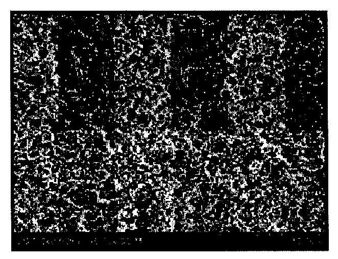
[0053]A polymer mixture of cyanoethylpullulan as a first binder polymer and polyvinylidene fluoride-co-hexafluoropropylene (PVdF-HFP) as a second binder polymer in a weight ratio of 2:10 was dissolved in acetone at 50° C. for at least about 12 hours to prepare a polymer solution. A barium titanate (BaTiO3) powder was added to the polymer solution until the weight ratio of the polymer mixture to the inorganic powder reached 10:90. The inorganic particles were crushed and dispersed using a ball mill for at least 12 hours to prepare a slurry. The inorganic particles of the slurry had an average particle diameter of 600 nm.

[0054]The slurry thus prepared was dip-coated on a 12 μm thick porous polyethylene terephthalate membrane (porosity 45%). The amount of the slurry loaded was adjusted to 12.5 g / m2.

[0055]Subsequently, distilled water as a non-solvent for the second binder polymer was sprayed on both surfaces of the slurry. The spray rate of the non-solvent was adjusted to 9 mL / min.

[005...

example 2

[0059]A separator was manufactured in the same manner as in Example 1, except that the kind of the non-solvent was changed to a mixture of distilled water and methanol (6:4 (v / v)).

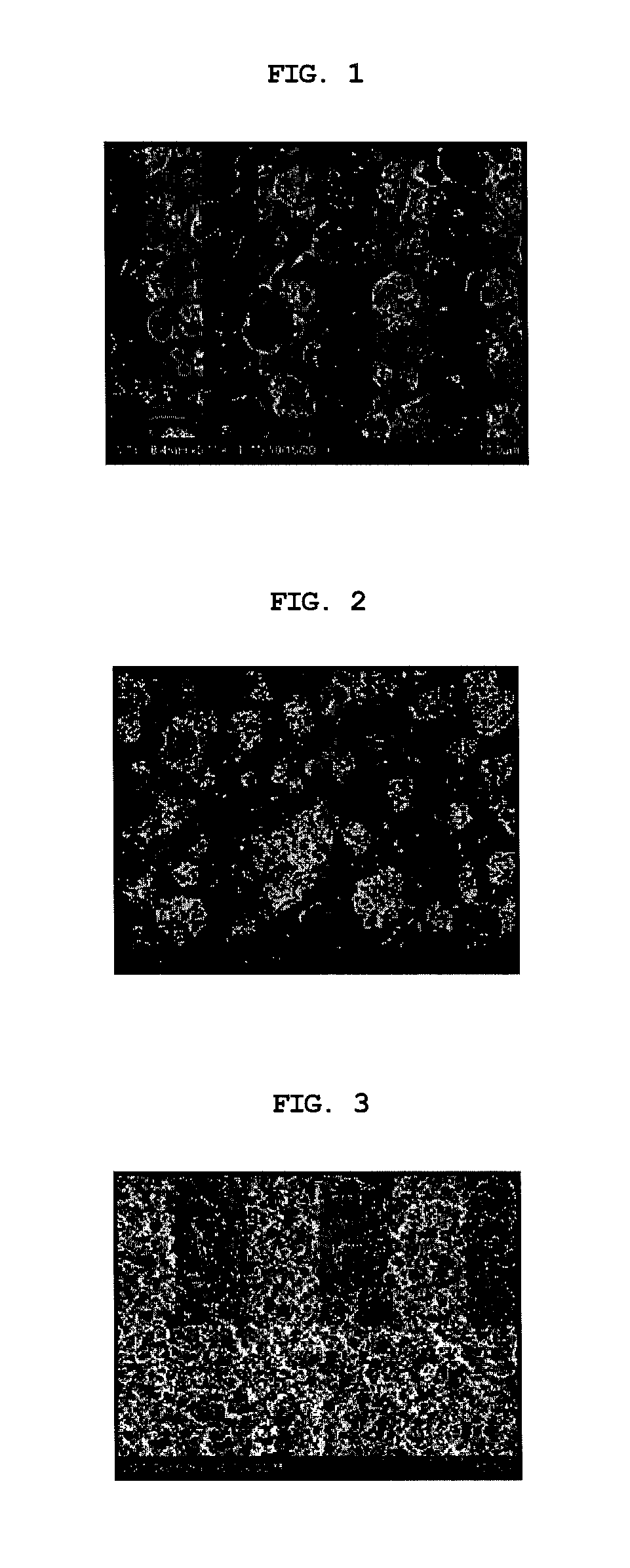
[0060]FIG. 2 is a SEM image showing the porous coating layer of the separator. From the image of FIG. 2, it can be confirmed that a large number of the second binder polymer molecules were exposed to the surface of the porous coating layer.

[0061]The separator was found to have a Gurley value of 371.1 sec / 100 mL and a bonding strength of 9.42 gf / cm.

example 3

[0062]A separator was manufactured in the same manner as in Example 1, except that the kind of the first binder polymer was changed to polycyanoacrylate. The separator was found to have a Gurley value of 364.9 sec / 100 mL and a bonding strength of 13.10 gf / cm.


PUM

PropertyMeasurementUnit
thicknessaaaaaaaaaa
particle diameteraaaaaaaaaa
dielectric constantaaaaaaaaaa

Abstract

Disclosed is a method for manufacturing a separator. The method includes (S1) preparing a porous planar substrate having a plurality of pores, (S2) preparing a slurry containing inorganic particles dispersed therein and a polymer solution including a first binder polymer and a second binder polymer in a solvent, and coating the slurry on at least one surface of the porous substrate, (S3) spraying a non-solvent incapable of dissolving the second binder polymer on the slurry, and (S4) simultaneously removing the solvent and the non-solvent by drying. According to the method, a separator with good bindability to electrodes can be manufactured in an easy manner. In addition, problems associated with the separation of inorganic particles in the course of manufacturing an electrochemical device can be avoided.

Description

CROSS-REFERENCE TO RELATED APPLICATION[0001]This application is a continuation of International Application No. PCT / KR2011 / 001371 filed Feb. 25, 2011, which claims priority under 35 USC 119(a) to Korean Patent Application Nos. 10-2010-0016990 and 10-2011-0016508 filed in the Republic of Korea on Feb. 25, 2010 and Feb. 24, 2011, respectively, the entire contents of which are incorporated herein by reference.TECHNICAL FIELD[0002]The present invention relates to a method for manufacturing a separator for an electrochemical device such as a lithium secondary battery, a separator manufactured by the method, and a method for manufacturing an electrochemical device including the separator. More specifically, the present invention relates to a method for manufacturing a separator in which a porous coating layer composed of a mixture of inorganic particles and binder polymers is formed on a porous substrate, a separator manufactured by the method, and a method for manufacturing an electroche...

Claims


Application Information

Patent Timeline
Patent Type & Authority Applications(United States)
IPC IPC(8): H01M2/16B05D5/12H01M10/04H01M50/403H01M50/417H01M50/42H01M50/423H01M50/426H01M50/429H01M50/443H01M50/489
CPCH01M2/145H01M2/16H01M2/162H01M2/166C08J5/2281C08J5/2287Y10T29/49115C08J2433/14C08J2433/26C08J2427/14Y02E60/12Y10T29/49108C08J2367/02Y02E60/10H01M50/409H01M50/411H01M50/44H01M50/446H01M50/403Y02P70/50H01M10/0525H01M10/02C08J7/04H01M50/423H01M50/42H01M50/429H01M50/489H01M50/426H01M50/417H01M50/443
Inventor LEE, JOO-SUNGHONG, JANG HYUKKIM, JONG-HUNRYU, BO-KYUNG
Owner TORAY BATTERY SEPARATOR FILM
Why Eureka
Try Eureka