
Method for polymerizing polypropylene

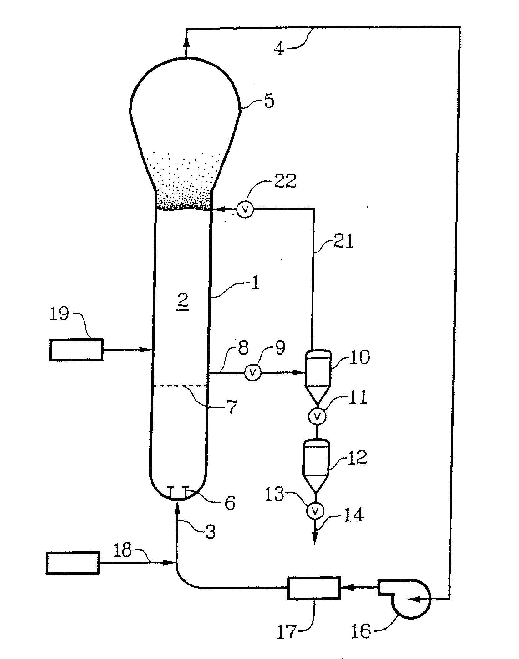
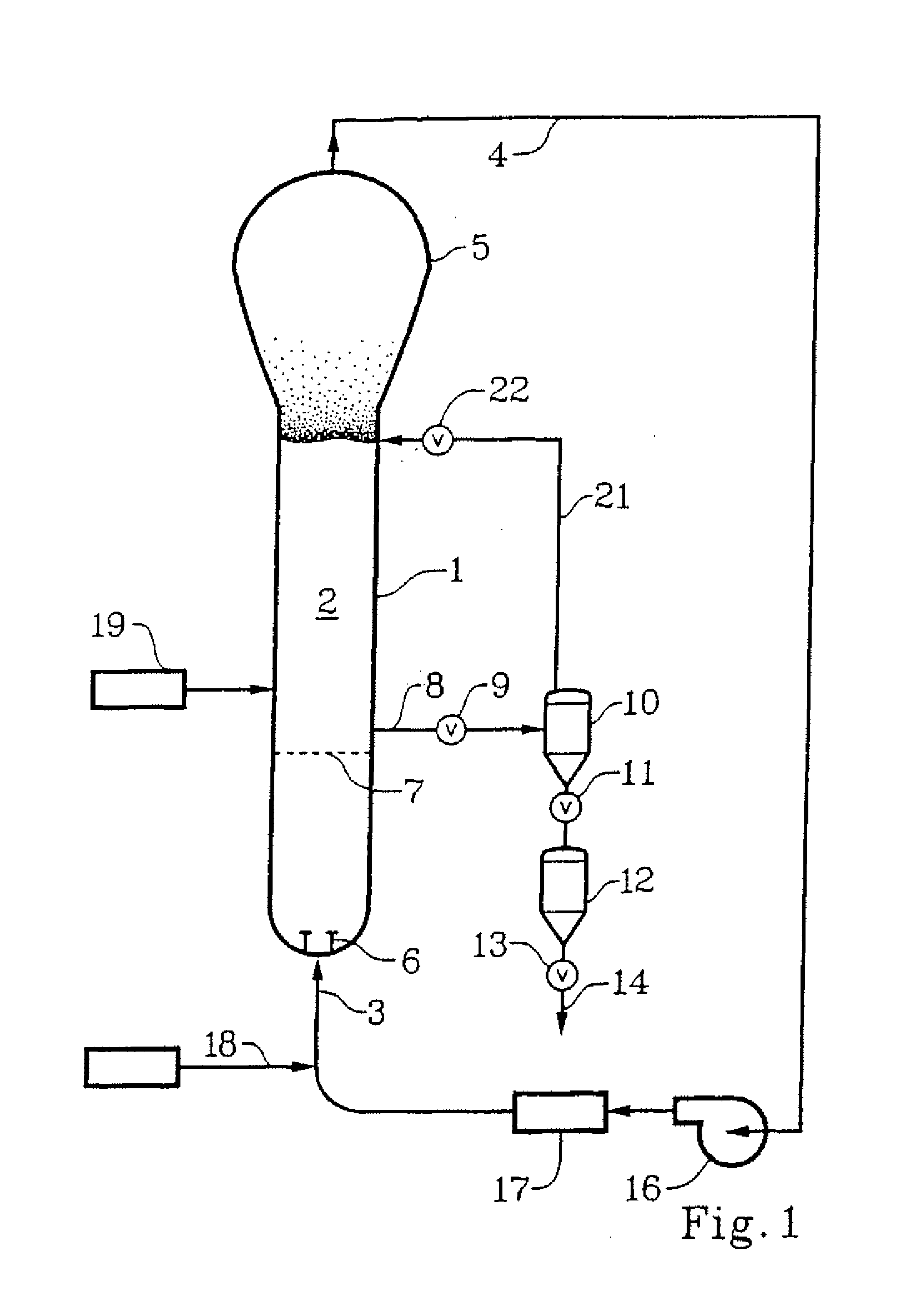
a polypropylene and polymerization technology, applied in the field of polyolefin production, can solve the problems of inefficiency, inoperable, and inability to allow the temperature of the vessel to increase, and achieve the effects of avoiding the risk of reactor fouling, high catalyst activity, and reducing investment and operation costs of polypropylene manufactur

Inactive Publication Date: 2012-05-10
WR GRACE & CO CONN
View PDF6 Cites 18 Cited by
  • Summary
  • Abstract
  • Description
  • Claims
  • Application Information

AI Technical Summary

Benefits of technology

[0004]Polypropylene reactors running in the condensing mode employing conventional Ziegler-Natta catalyst systems typically are operated such that the difference between the temperature of the fluidized bed and the dew point temperature of the recycle gas (also known as the “bed minus dew temperature”) is small, typically about 1-2° C. This relatively small bed minus dew value results in an amount of liquid propylene being present in the reactor. The liquid propylene is considered advantageous as it serves to absorb heat of reaction (particularly during production spikes or production irregularities or production interruptions) and also serves to prevent reactor fouling. It is generally understood in the art that the bed minus dew temperature must be small in order to ensure that liquid propylene monomer is present in the reactor.
[0005]However, it has recently been discovered that the use of certain catalyst systems, such as those described in WO2009 / 029487, avoids the risk of reactor fouling independent of the presence of liquid propylene. Consequently, the bed minus dew value may be increased without any adverse impact on the reaction and / or polymer.
[0006]The increase of bed minus dew can be associated with a lower reactor total pressure and / or a higher reactor temperature.
[0007]When the reactor total pressure is relatively low, the investment and operation costs of polypropylene manufacture can be reduced. Previously, a relatively higher reactor total pressure (e.g., 450-500 psi) was always preferred, because of the need for a high monomer partial pressure to maintain a high catalyst activity. With the recently developed high activity catalysts systems, a relatively lower reactor total pressure, with a desired balance of catalyst activity and the investment / operational cost reduction, can be achieved for the purpose of minimizing manufacturing cost.
[0008]When the reactor temperature is relatively high, a few desired changes can occur accordingly, including higher catalyst activity, lower oligomer level in product (hence less volatile organic compounds (VOC) and odor), lower xylene solubles (XS), narrower molecular weight distribution, higher heat-removal driving force (hence easier to remove reaction heat), etc. In some cases, a higher reactor temperature can also help to produce product with higher melt flow rate (MFR), so to reduce or eliminate the need of energy-consuming visbreaking process needed for manufacturing high MFR products.
[0009]Despite the use of such new catalyst systems, it is still generally believed that the reactor should be operated at a bed minus dew temperature of less than 10° C. in order to avoid static build-up or fouling (see examples in WO2009 / 029487). However, it has been discovered that gas phase reactors using these catalyst systems can be operated at bed minus dew temperatures greater than previously expected without fouling or static problems. This allows the reactor to be run at higher temperatures than previously thought possible at a given total pressure, or alternatively to run the reactor at a lower total pressure at a given reactor temperature, or both.

Problems solved by technology

In addition, the temperature of the vessel cannot be permitted to increase to the point where the product particles become sticky and adhere to each other.
The earliest such recycle systems were based on the assumption that it would be inefficient, or inoperable, to cool the recirculating gas below its dew point so that liquid would be introduced into the reactor through the recycle process.

Method used


Image

  • Method for polymerizing polypropylene
  • Method for polymerizing polypropylene
  • Method for polymerizing polypropylene

Examples


examples

[0073]The following Examples were run to demonstrate the advantages in terms of catalyst consumption and pressure reduction obtainable by using the method of the present invention in two different catalyst systems.

ExampleComp. AA1A2Comp. BB1B2CatalystZ-N (see U.S. Pat.Z-N (see U.S. Pat.No. 5,317,036)No. 5,604,172)Donor95% DBS (di-n-butyl sebacate) + 5% “C Donor”(methylcyclohexyldimethoxysilane)ReactorGas-Phase Fluidized-Bed Unipol Reactor, 18.25 ftdiameter, 65 ft straight section heightProductPolypropyleneRandom Ethylene-HomopolymerPropylene CopolymerProduction5050Rate(Ton / hr)Reactor T727272657272(° C.)Reactor P490375300450375300(psig)Gas Composition (mol %)propylene77.2380.7779.3766.1378.8579.37hydrogen0.310.320.320.260.310.31propane9.6112.6913.6113.5112.6213.28nitrogen12.856.226.719.087.015.83ethylene0001.011.211.22Dew Point64.758.748.655.657.448.6(° C.)Bed - Dew7.313.323.49.414.623.4(° C.)Residence1.01.952.001.092.112.15Time (hr)Catalyst100%75.4%86.0%100%68.9%75.0%consump-tion*

[0...


PUM

PropertyMeasurementUnit
temperatureaaaaaaaaaa
total pressureaaaaaaaaaa
reactor temperatureaaaaaaaaaa

Abstract

The present disclosure relates to a method for polymerizing polypropylene, optionally with one or more additional comonomers in a gas phase reactor in the presence of a mixed electron donor system comprising at least one selectivity control agent and at least one activity limiting agent. The process involves controlling the polymerization process to ensure that the difference between the reactor temperature and the dew point temperature of the incoming monomer stream is 12° C. or greater.

Description

[0001]The present disclosure relates to a method for polymerizing polypropylene, optionally with one or more additional comonomers in a gas phase reactor in the presence of a mixed electron donor system comprising at least one selectivity control agent and at least one activity limiting agent. The process involves controlling the polymerization process to ensure that the difference between the reactor temperature and the dew point temperature of the incoming monomer stream is 12° C. or greater.BACKGROUND AND SUMMARY OF THE INVENTION[0002]The production of polyolefins in gas phase reactors, such as fluidized bed reactors, requires that the heat of reaction be removed in order to maintain appropriate temperatures for the desired reaction rate. In addition, the temperature of the vessel cannot be permitted to increase to the point where the product particles become sticky and adhere to each other. The heat of reaction is commonly removed by circulating the gas from the fluidized bed to...

Claims


Application Information

Patent Timeline
Patent Type & Authority Applications(United States)
IPC IPC(8): C08F2/34
CPCC08F10/06C08F210/06C08F110/06C08F10/00C08F2/34C08F210/16C08F4/6494C08F4/6465
Inventor VAN EGMOND, JAN W.CAI, PING
Owner WR GRACE & CO CONN
Learn More