System and device for correcting hyperopia, myopia and presbyopia

a hyperopia and system technology, applied in the field of human and/or mammalian ophthalmic sciences, can solve the problems of increasing the optical refraction power of the lens, many refractive errors of the human eye, etc., and achieve the effects of reducing sliding friction, and reducing the risk of eye damag

Inactive Publication Date: 2012-05-10
SHAHINPOOR MOHSEN +2
View PDF2 Cites 7 Cited by
  • Summary
  • Abstract
  • Description
  • Claims
  • Application Information

AI Technical Summary

Benefits of technology

[0033]Here by hydrophilic coating of the limbus rings means when in the presence of water or body fluids, the hydrophilic polymer adsorbs water molecules to create a watery interface at the surface of the plastic ring to reduce sliding friction between the ring and the cornea.
[0034]The present invention is described herein with reference to a number of example embodiments. In particular, the present invention includes a system to correct nearsightedness or myopia in a human and/or mammalian eye by the use of a limbus ring to be mounted on the limbus annulus of an eye by an ophthalmic or optometric physician, for example by being press-fitted or pre-compressed fitted. The heat shrink ring can be made inherently electrically conductive and thus can be heated transcutaneously by magnetic inductive heating to shrink to correct tension. By using the limbus ring, one can actively change the corneal curvature as well as the axial length of the eye in order to induce refractive error correction for hyperopia.
[0035]In another example embodiment, the present invention teaches a myopia (nearsightedness) correction method and the associated system in the form of limbus ring with hydrophilic coating mounted on the limbus annulus of an eye by an ophthalmic or optometric physician, for example by being press-fitted, pre-compressed fitted or heat shrink fitted, in an encircling relation to the central optic zone of the cornea by means of a deployment devi...

Problems solved by technology

There are many refractive errors associated with the human eye.
This allows the elastic capsule of the lens to contra...

Method used


Image

  • System and device for correcting hyperopia, myopia and presbyopia
  • System and device for correcting hyperopia, myopia and presbyopia
  • System and device for correcting hyperopia, myopia and presbyopia

Examples


Embodiment Construction

[0068]The following description of various example embodiments of the invention is not intended to limit the invention to any single preferred embodiment, but rather to enable any person skilled in the ophthalmic arts to make and use the invention.

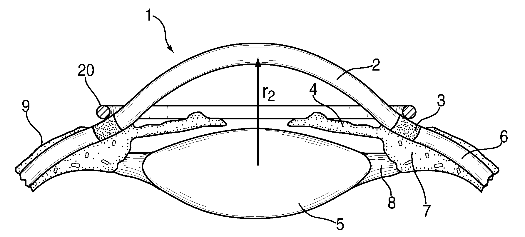
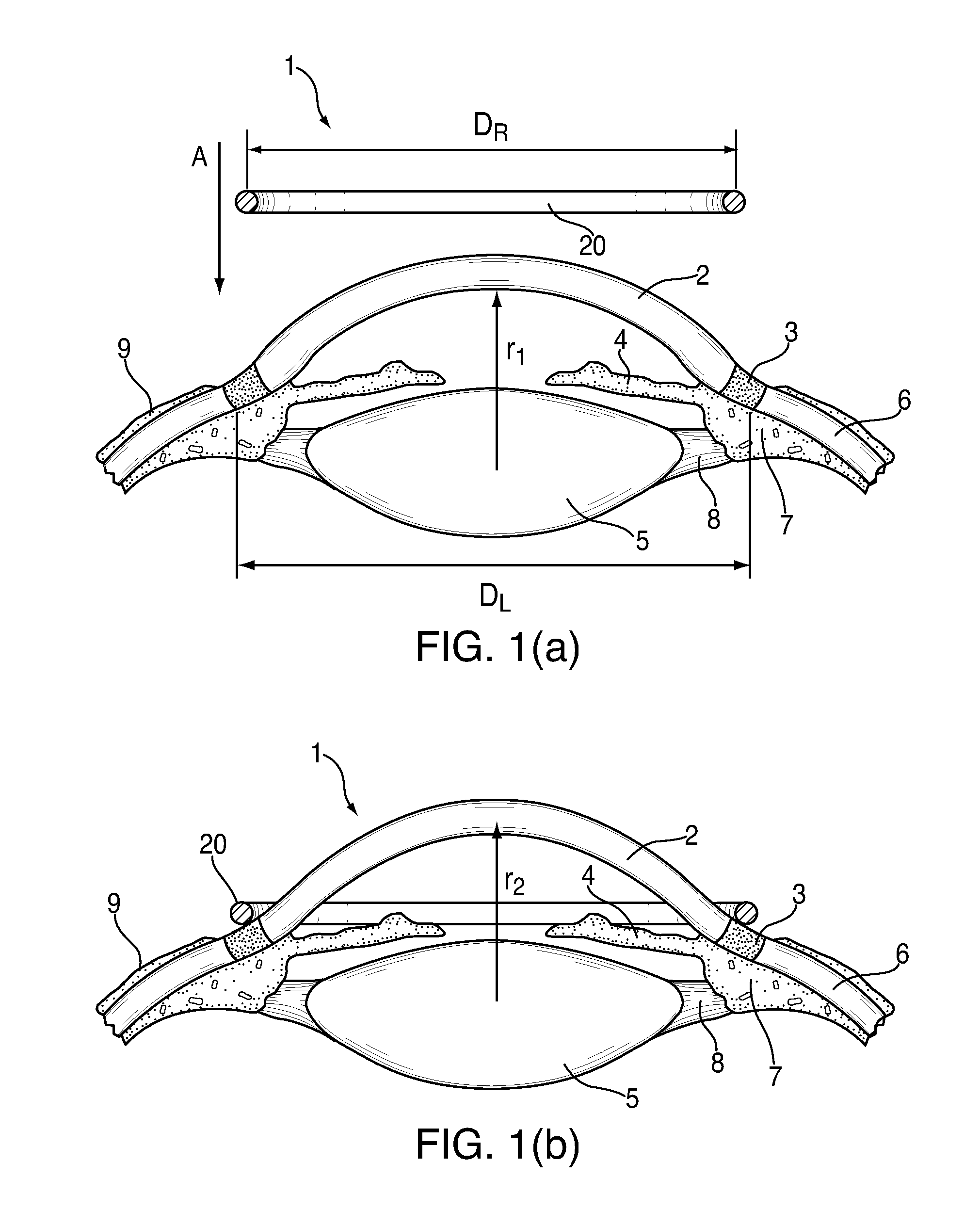
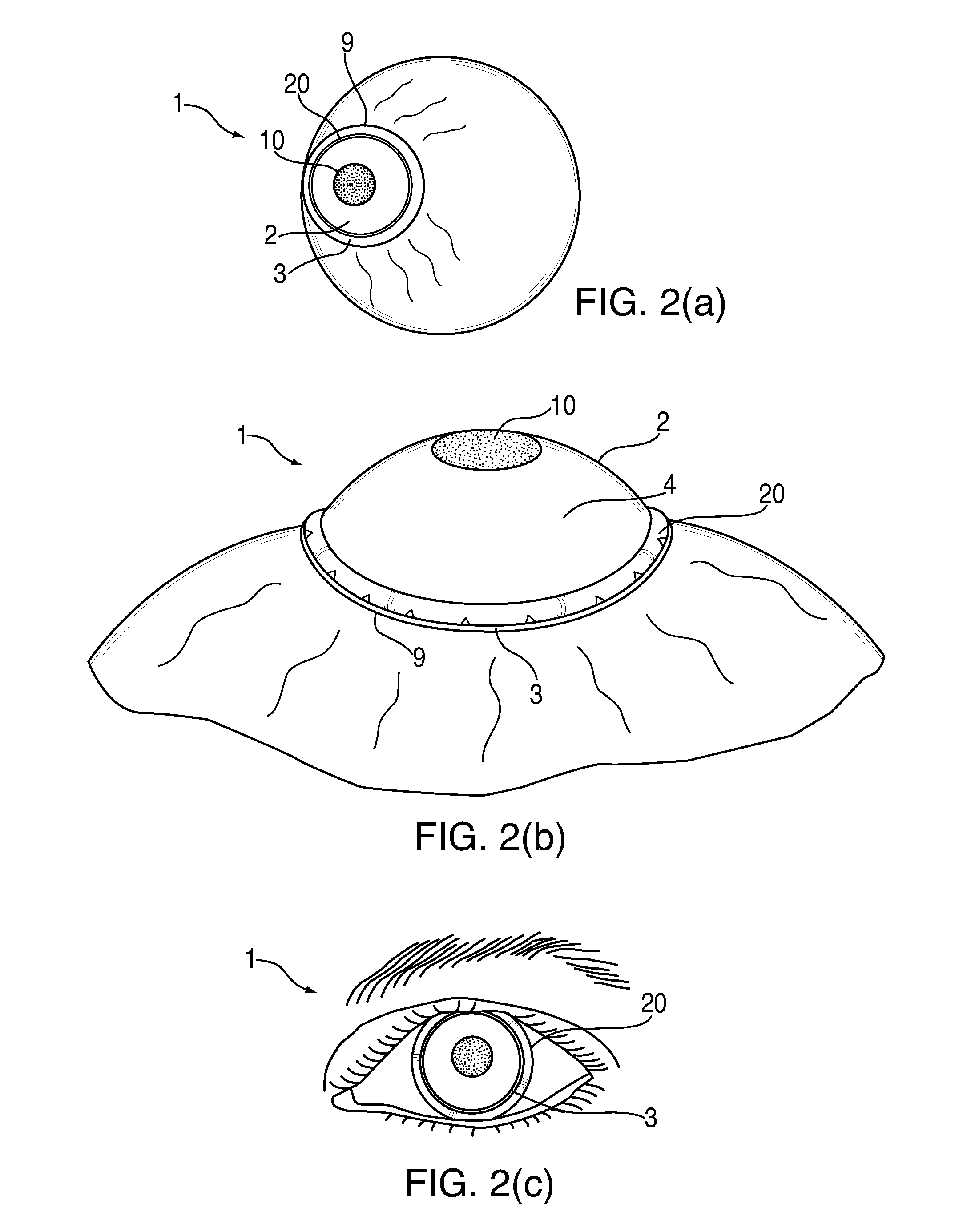
[0069]Example embodiments of the present invention create changes in eye length and corneal curvature to correct hyperopia, myopia and presbyopia. The example embodiments further teach a hyperopia (farsightedness) correction method and the associated system in the form of a limbus ring with hydrophilic coating mounted on the limbus annulus of an eye by an ophthalmic or optometric physician, for example by being press-fitted, pre-tensioned fitted, pre-compressioned fitted or heat shrink fitted, in an encircling relation to the central optic zone of the cornea by means of a deployment device.

[0070]The limbus ring of the example embodiments is mountable through the use of ophthalmic glue, medical grade RTV (silicone adhesive), sutures or an e...


PUM


Abstract

The present invention includes an ophthalmic device and system of mounting for correcting hyperopia, myopia and presbyopia. The present invention includes a limbus ring mountable in an encircling relation to a central optic zone of a cornea on a limbus annulus surrounding the cornea. In the limbus ring defines a substantially annular toroid defining a first average diameter that is selectable and has a hydrophilic coating disposed thereon. The inner radius of the limbus ring is selectable such that, upon mounting on the limbus annulus, the limbus ring causes the limbus annulus to contract or expand thereby causing the curvature of the cornea and the eye length to increase or decrease. The mounting system of the present invention is adapted to receive a limbus ring and further adapted to selectively place the limbus ring on a limbus annulus.

Description

CROSS REFERENCE TO RELATED APPLICATIONS[0001]This application claims priority as a continuation in part of U.S. application Ser. No. 11 / 626,774, filed Jan. 24, 2007, which application is incorporated herein by reference.TECHNICAL FIELD[0002]The present invention relates generally to the field of human and / or mammalian ophthalmic sciences, and more particularly to a system and device for correcting hyperopia, myopia and presbyopia in the human and / or mammalian eye.BACKGROUND[0003]There are many refractive errors associated with the human eye. When the focal point of images is formed in front of the retina / macula region due to excess refraction of light rays, the refractive error is called myopia or near-sightedness. When, on the other hand, the focal point of images lie outside the eye behind the retina / macula region due to insufficient refraction of light rays, the refractive error is called either hyperopia or far-sightedness or presbyopia. These problems can be surgically correcte...

Claims


Application Information

Patent Timeline
IPC IPC(8): A61F2/14
CPCA61F2/147
Inventor SHAHINPOOR, MOHSENSOLTANPOUR, DAVIDSHAHINPOOR, PARSA
Owner SHAHINPOOR MOHSEN
Why Eureka
Try Eureka