Device and method to control a power source

a technology of power source and control circuit, which is applied in the direction of soldering apparatus, welding devices, manufacturing tools, etc., can solve the problems of noise, sensitivity problems, complicated and electrically demanding control circuit, etc., and achieve the effect of preventing electrical shock

Active Publication Date: 2012-05-17
LINCOLN GLOBAL INC
View PDF6 Cites 30 Cited by
  • Summary
  • Abstract
  • Description
  • Claims
  • Application Information

AI Technical Summary

Benefits of technology

[0005]Embodiments of the present invention comprise devices and methods for providing voltage reduction capability in welding power sources for safety purposes. The resistive load and the output voltage of the welding power source output are monitored and compared to predefined or preselected threshold values to generate a load/no-load condition signal and a high/low output voltage condition signal (e.g., logic signals). The load/no-load condition signal and the high/low output voltage condition signal serve as inputs t

Problems solved by technology

In order to reduce the open circuit voltage to a low level, the minimum conduction period of the switching devices requires a complicated an

Method used


Image

  • Device and method to control a power source
  • Device and method to control a power source
  • Device and method to control a power source

Examples


first embodiment

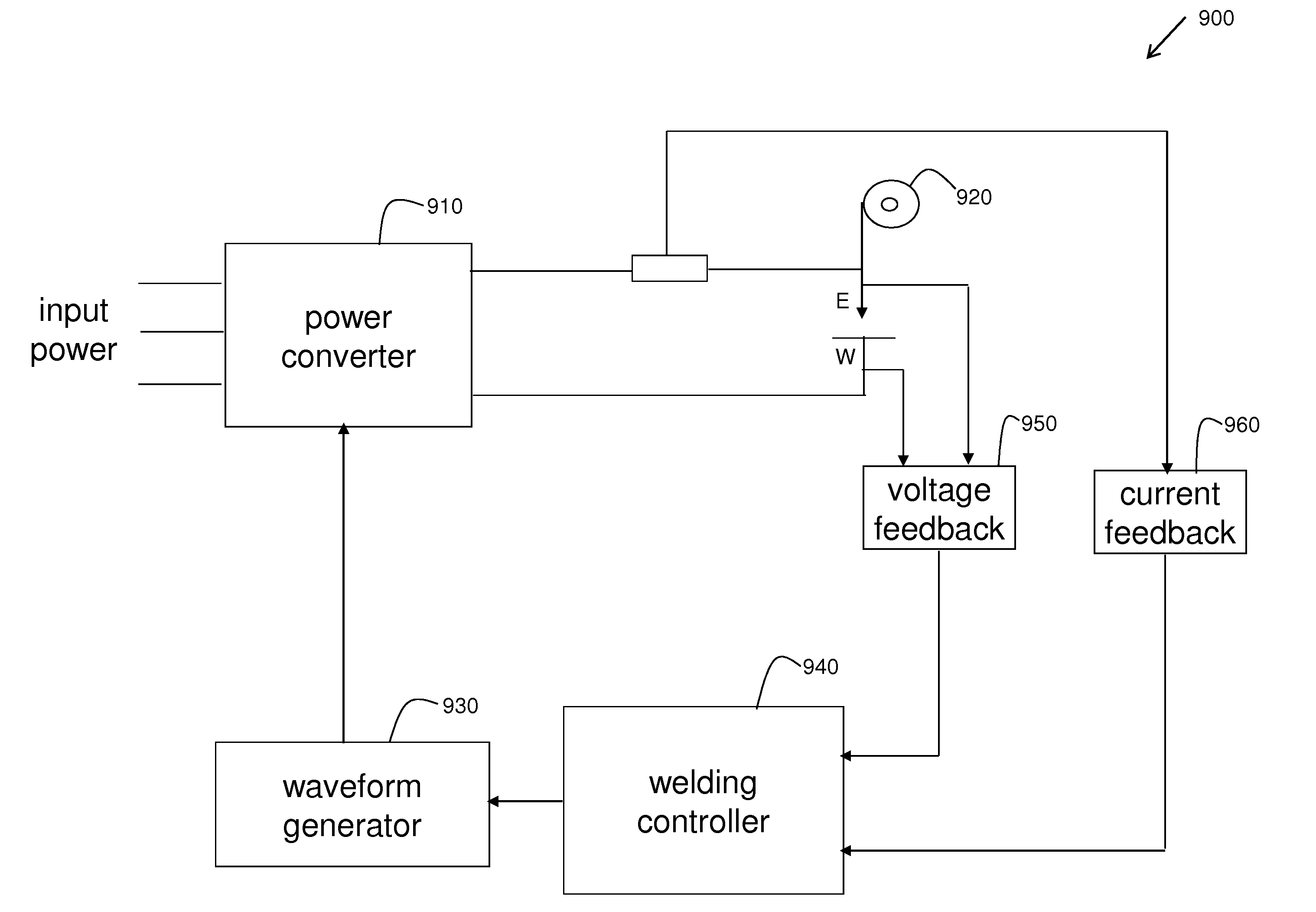
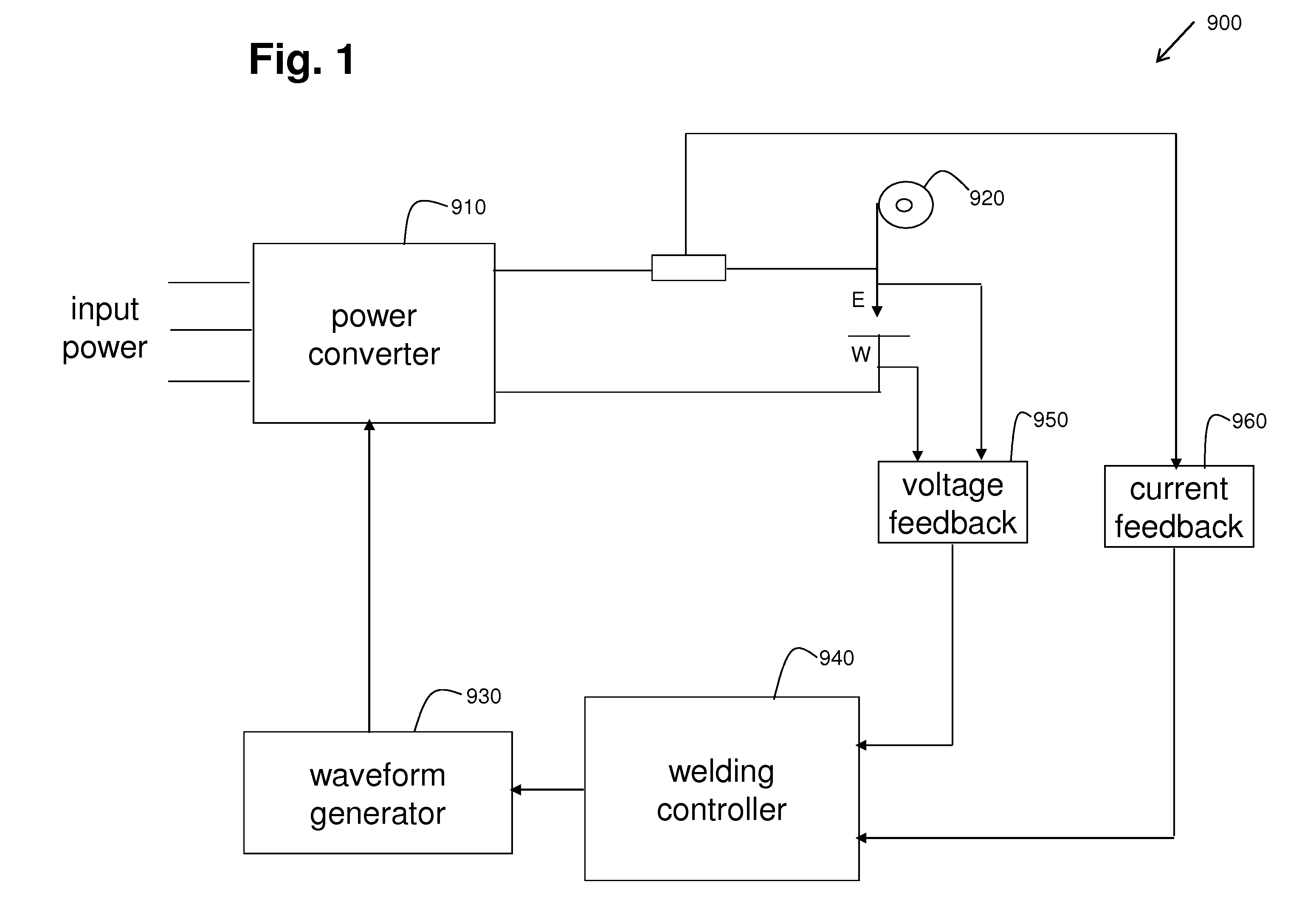
[0030]FIG. 3 illustrates a schematic block diagram of an example embodiment of an improved voltage reduction device implemented in a welding power source 300 that may be implemented in the electric arc welding system 900 of FIG. 1. FIG. 3 shows an input power side of the power source 300, being on the primary side of a welding transformer 310, and an output power side of the power source, being on the secondary side of the welding transformer 310.

[0031]The input power side of the power source 300 in FIG. 3 includes the primary winding 311 of the single phase welding transformer 310 along with an input power contact relay CR having an energizing coil 321 and a set of electrical relay contacts 322. The primary winding 311 and the relay contacts 322 are in series with an input power source VIN when VIN is applied to the input of the power source 300. The input power side also includes an auxiliary transformer 330 having a primary side connected to VIN and a secondary side connected to ...

second embodiment

[0042]FIG. 4 illustrates a schematic block diagram of an example embodiment of an improved voltage reduction device implemented in a power source 400 of the electric arc welding system 900 of FIG. 1. The power source 400 of FIG. 4 is very similar to the power source 300 of FIG. 3 except that the output power side of the power source 400 of FIG. 4 is configured a little differently as a single phase full bridge configuration. Instead of having a single secondary winding as in FIG. 3, FIG. 4 shows a welding transformer 410 having two secondary windings 412 and 413 and two SCR's 495 and 496. The output controller 399 is configured to enable and disable such a configuration of output components. The VRD components of FIG. 4 are the same as that of FIG. 3, however, and VRD capability and operation are the same.

[0043]FIG. 5 illustrates a schematic block diagram of an example embodiment of an improved voltage reduction device implemented in a generic embodiment of a power source 500 of the...


PUM

PropertyMeasurementUnit
Electrical resistanceaaaaaaaaaa
Poweraaaaaaaaaa
Electrical resistanceaaaaaaaaaa

Abstract

Apparatus, devices, and methods for providing a voltage reduction capability in a welding power source for safety purposes. The resistive load and the output voltage of the welding power source output are monitored and compared to predefined or preselected threshold values to generate a load condition signal and an output voltage condition signal (e.g., logic signals). The load condition signal and the output voltage condition signal serve as inputs to a voltage reduction device control logic which generates control signals to enable and disable the input and output of the welding power source according to the defined control logic. As a result, an extra measure of safety in preventing electrical shock is provided to users of the welding power source during hazardous operating conditions.

Description

[0001]The description of the preferred embodiment section and the drawings of U.S. Pat. No. 7,238,917 issued on Jul. 3, 2007 are incorporated by reference herein in their entirety.TECHNICAL FIELD[0002]Certain embodiments relate to welding power sources. More particularly, certain embodiments relate to devices and methods for providing a voltage reduction capability in welding power sources for safety purposes.BACKGROUND[0003]Several techniques have been used to reduce the open circuit voltage of an arc welding power source before the welder is to be used for a welding process. One of the most common designs is a control circuit that reduces the conduction period of the output switching devices, so the open circuit voltage is retained at a desired lower value. In an inverter type power source, the switching devices are usually in the form of field effect transistors (FETs) or insulated gate bi-polar transistors (IGBTs). Since the switching frequency is usually greater than 20 kHz, th...

Claims


Application Information

Patent Timeline
IPC IPC(8): B23K9/10
CPCB23K9/1006B23K9/1031B23K37/006
Inventor STAVA, ELLIOTT K.CLARK, KEITH L.
Owner LINCOLN GLOBAL INC
Why Eureka
Try Eureka