Capacitive load driving circuit, liquid ejecting apparatus, and medical apparatus

a technology of driving circuit and liquid ejector, which is applied in the direction of printing, other printing apparatus, etc., can solve the problems of large circuit substrate size, low power efficiency, and high power consumption, and achieve the effect of suppressing the resonance characteristics of low-pass filter, high accuracy and stabl

Inactive Publication Date: 2012-05-17
COLUMBIA PEAK VENTURES LLC
View PDF1 Cites 21 Cited by
  • Summary
  • Abstract
  • Description
  • Claims
  • Application Information

AI Technical Summary

Benefits of technology

[0008]An advantage of some aspects of the invention is that it provides a technique for generating a stable drive signal with high accuracy while suppressing the resonance characteristics of a low pass filter, even in case where a frequency component of the drive signal is set to be raised as high as several hundreds of kHz or there is an external disturbance, increasing the power efficiency, and decreasing the size of a circuit substrate.
[0011]Accordingly, the compensation for smoothing the gain characteristics in the frequency band of the drive signal is performed for the drive signal applied to the capacitive load, and negative feedback of the compensated driving signal is applied, whereby the resonance characteristics due to the LC circuit of the low pass filter can be suppressed. In addition, the power amplification is performed for the pulse-modulated signal, and accordingly, extra power is not consumed at the time of amplifying the power, and the size of the circuit substrate can be configured to be small. Furthermore, although the negative feedback of the drive signal or the modulation for forming a modulated signal is performed in the form of a digital signal, compensation for the drive signal when the negative feedback of the drive signal is applied is performed by an analog circuit, and accordingly, the delay time required for the negative feedback can be short. As a result, regardless of the negative feedback of the drive signal, even in a case where the frequency component of the drive signal is set to be high up to several hundreds of kHz, a stable drive signal can be output.
[0013]In the case of the subtraction circuit, digital calculation can be performed in a speedy manner so as to shorten the delay time at the time of the negative feedback, whereby drive signal can be output stably.
[0015]Since the drive signal applied to the capacitive load is a voltage waveform smoothed by the low pass filter, the drive signal is a voltage waveform of which phase lags with respect to that of the drive waveform signal that is used as the reference. Accordingly, in a case where negative feedback is performed after performing phase-leading compensation when the negative feedback of the drive signal is applied, the occurrence of a resonance phenomenon due to the negative feedback can be suppressed, whereby the drive signal can be avoided from being unstable.
[0017]In such a case, the effect of applying the negative feedback after performing the phase-leading compensation for the drive signal and the effect of dividing the voltage of the drive signal and applying the negative feedback can be acquired. Accordingly, even in a case where the magnitude of the capacitive component (or an inductive component) of the capacitive load varies, a power supply voltage varies at the time of amplifying the modulated signal, unbalance in various elements configuring the capacitive load driving circuit occurs, or the like, it is possible to suppress the occurrence of distortion in the drive signal. In addition, since the composed analog signal is converted into a digital signal, the capacitive load driving circuit can be realized by using only one A / D converter.

Problems solved by technology

In a case where the driving signal is generated by using an analog amplifier circuit, a large current flows through the circuit, whereby the power consumption is high.
As a result, the power efficiency is low, and the size of a circuit substrate is large.
In addition, since the consumed power is converted into heat, a large heat radiation plate is necessary, whereby the size of the substrate further increases.
However, according to the proposed technique, since the low pass filter is configured by the LC circuit, there is a resonance characteristic in a high-frequency band, whereby it is difficult to acquire a desired drive signal.
However, according to such a method, power is consumed when a current flows through the resistor, and accordingly, an original purpose of decreasing the size in the circuit substrate by improving the power efficiency diminishes.
However, according to the proposed technique, the digital signal processing of the state stabilizing mechanism is complicated, and it takes ten to several tens of clocks to complete the process, and accordingly, a delay time required for negative feedback is long.
In addition, in a case where a specified capacitive load to be driven changes, there is a problem in that the drive signal may be distorted.
As a result, the acquired drive signal is distorted due to the influence of the change in the frequency characteristics.
In addition, in a case where a piezoelectric device is used as an actuator built in an attachment for an apparatus that is used with attachments having different characteristics being attached in a switched manner, a similar problem may occur.
In other words, since the magnitude of the capacitive component of the piezoelectric device differs depending on the installed attachment, the frequency characteristics of the low pass filter changes, and accordingly the drive signal may be distorted.
Furthermore, although the negative feedback of the drive signal or the modulation for forming a modulated signal is performed in the form of a digital signal, compensation for the drive signal when the negative feedback of the drive signal is applied is performed by an analog circuit, and accordingly, the delay time required for the negative feedback can be short.

Method used


Image

  • Capacitive load driving circuit, liquid ejecting apparatus, and medical apparatus
  • Capacitive load driving circuit, liquid ejecting apparatus, and medical apparatus
  • Capacitive load driving circuit, liquid ejecting apparatus, and medical apparatus

Examples


first embodiment

A. FIRST EMBODIMENT

A-1. Apparatus Configuration

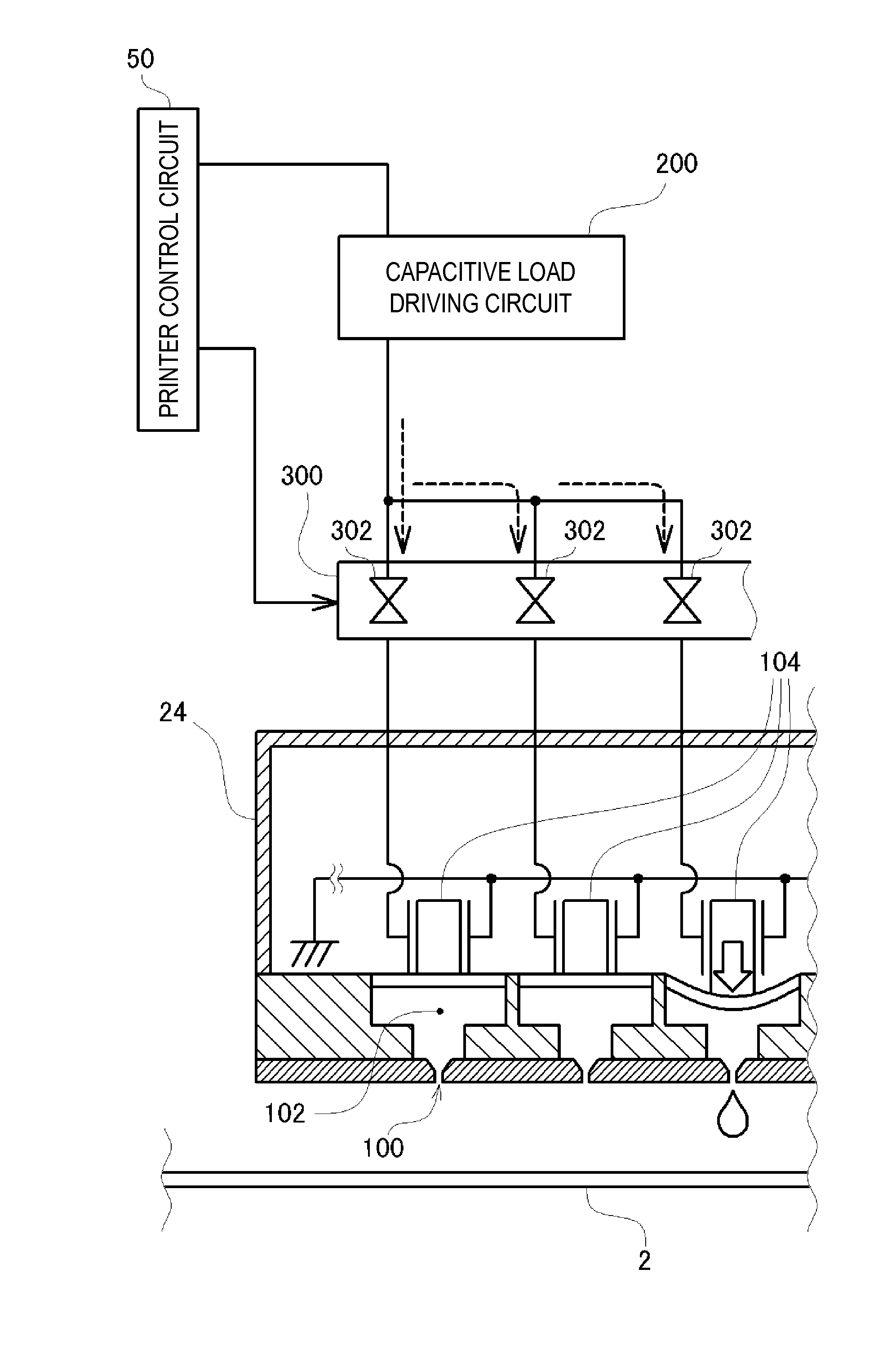
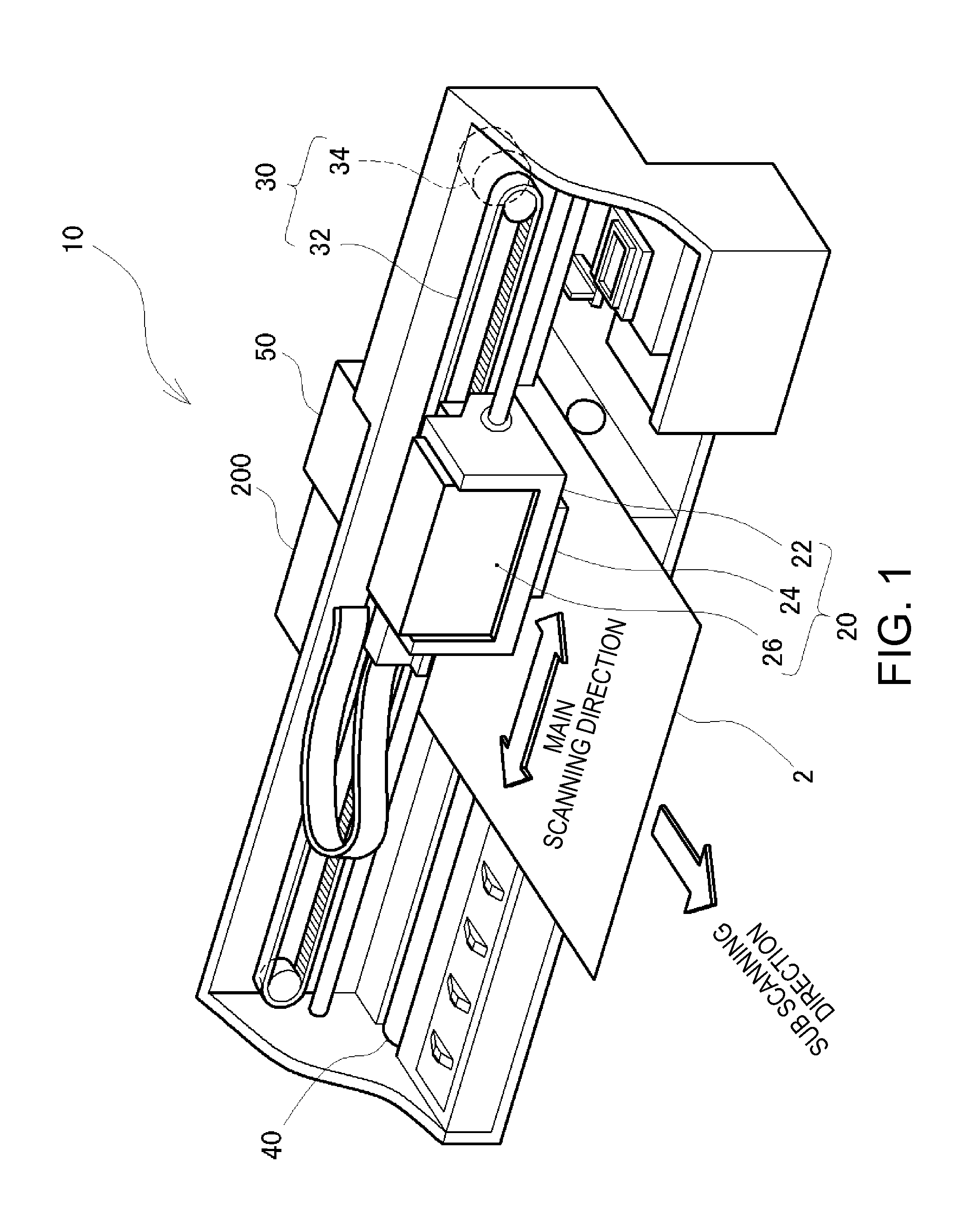
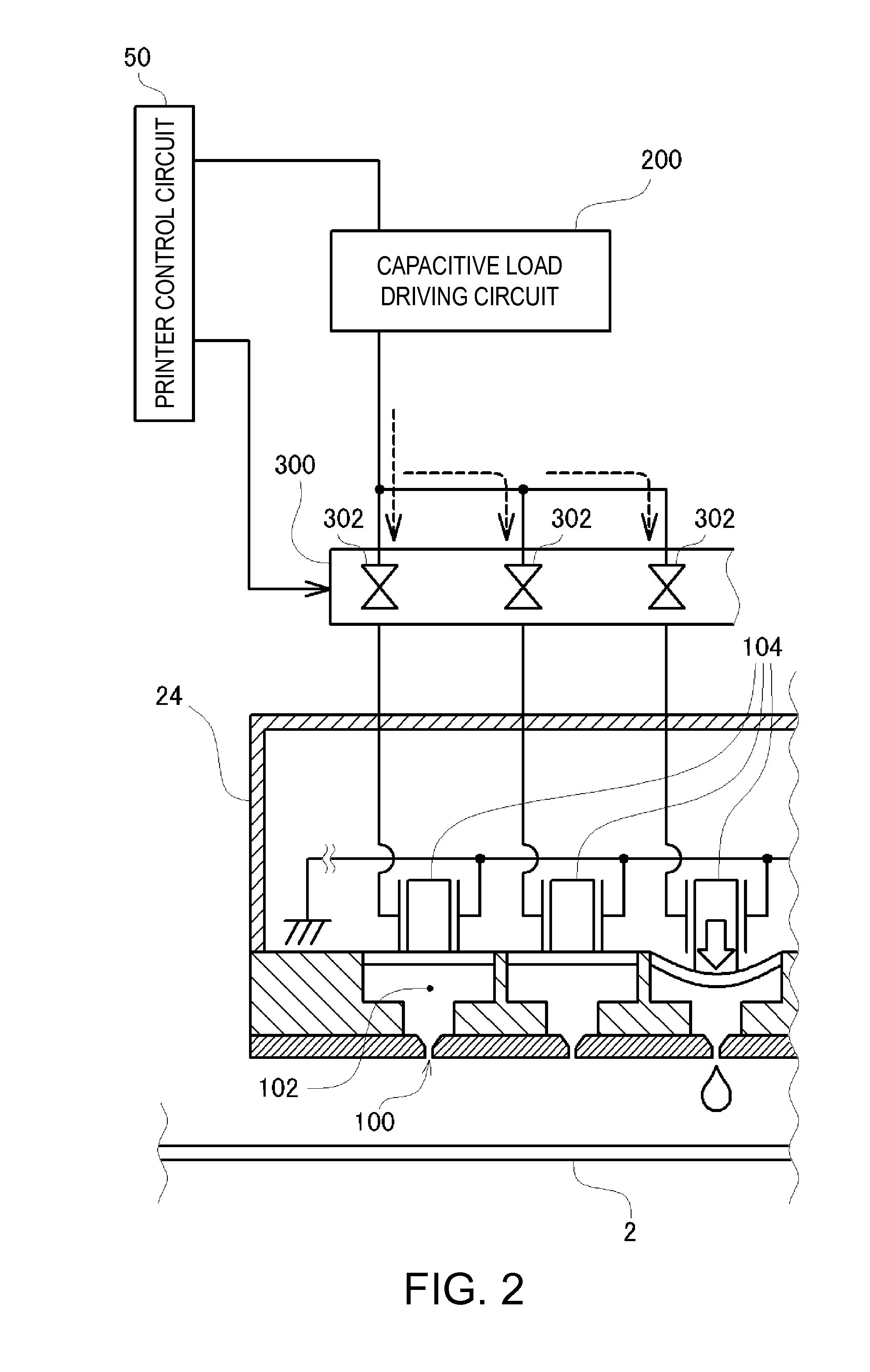
[0046]FIG. 1 is an explanatory diagram illustrating an example of an ink jet printer 10 in which a capacitive load driving circuit according to an embodiment is mounted. The ink jet printer 10 includes: a carriage 20 that forms ink dots on a printing medium 2 while reciprocating in the main scanning direction; a driving mechanism 30 that allows the carriage 20 to reciprocate; a platen roller 40 that is used for feeding the printing medium 2; and the like. In the carriage 20, an ink cartridge 26 that houses ink, a carriage case 22 in which the ink cartridge 26 is mounted, an ejection head 24 that is installed to the bottom side (the side facing the printing medium 2) of the carriage case 22 and ejects ink, and the like are disposed. The carriage 20 guides ink located inside the ink cartridge 26 to the ejection head 24, and ejects ink from the ejection head 24 onto the printing medium 2, thereby printing an image.

[0047]The driving mechani...

second embodiment

B. SECOND EMBODIMENT

[0071]In the capacitive load driving circuit 200 according to the first embodiment described above, by suppressing an increase in the gain near the resonance frequency of the low pass filter 226, the drive signal is prevented from being distorted. However, actually, in a case where the magnitude of the capacitive component (or inductive component) of the capacitive load remarkably increases, the frequency characteristics of the low pass filter change, and slight distortion in the drive signal appears.

[0072]FIG. 9 is an explanatory diagram illustrating a change in the gain characteristics in accordance with a remarkable increase in the capacitive component of the capacitive load of the capacitive load driving circuit 200 according to the first embodiment. In the figure, characteristics denoted by a broken line are the gain characteristics before a remarkable increase in the capacitive component of the capacitive load, and characteristics denoted by a solid line in...

first modified example

C-1. First Modified Example

[0080]In the above-described first or second embodiment, the capacitive load driven by applying a drive signal thereto is described as the piezoelectric device 104 disposed inside the ejection head 24. As described above, since the number of the piezoelectric devices 104 to be driven changes to a large extent during a printing process, the magnitude of the capacitive component of the capacitive load greatly changes. However, the capacitive load to be driven is not limited to the piezoelectric device 104 disposed inside the ejection head 24, and any capacitive load may be used as long as the magnitude of its capacitive component changes. For example, even in a case where a liquid pump that ejects liquid using a piezoelectric device is driven, the capacitive load driving circuit 200 according to the first embodiment or the capacitive load driving circuit 250 according to the second embodiment can be appropriately applied.

[0081]FIG. 13 is an explanatory diagr...


PUM


Abstract

A modulated signal is generated by performing pulse modulation of a drive waveform signal that is a reference for a drive signal to be applied to a capacitive load, and the drive signal is generated by performing power amplification of the acquired modulated signal and then smoothing the power-amplified modulated signal. Then, negative feedback of the drive signal applied to the capacitive load is applied to the drive waveform signal that is the reference for the drive signal. At this time, a predetermined analog compensation process for smoothing gain characteristics in a frequency band included in the drive signal is performed for the drive signal, then the acquired signal is converted into a digital signal, and negative feedback of the digital signal is applied to the drive waveform signal.

Description

BACKGROUND[0001]1. Technical Field[0002]The present invention relates to a technique for driving a capacitive load of which a capacitive component changes or a technique for driving a plurality of capacitive loads having different capacitive components in a switching manner.[0003]2. Related Art[0004]There are many actuators, which operate by applying a predetermined driving signal thereto, such as an ejection head mounted in an ink jet printer and the like. In a case where the driving signal is generated by using an analog amplifier circuit, a large current flows through the circuit, whereby the power consumption is high. As a result, the power efficiency is low, and the size of a circuit substrate is large. In addition, since the consumed power is converted into heat, a large heat radiation plate is necessary, whereby the size of the substrate further increases.[0005]Thus, a technique is proposed in which a drive waveform signal as a reference for a drive signal is converted into a...

Claims


Application Information

Patent Timeline
Patent Type & Authority Applications(United States)
IPC IPC(8): B41J29/38
CPCB41J2/04541B41J2/04588B41J2/04581B41J2/04573
Inventor OSHIMA, ATSUSHITABATA, KUNIOYOSHINO, HIROYUKIIDE, NORITAKA
Owner COLUMBIA PEAK VENTURES LLC
Why Eureka
Try Eureka