
Multiple resolution continuous ink jet system

a continuous ink jet, multi-resolution technology, applied in the direction of printing, inking apparatus, etc., can solve the problems of reducing limiting the usefulness of drop-on-demand emitters for high, and reducing print quality not only by resolution reduction, so as to reduce overall equipment costs and improve print job flexibility

Active Publication Date: 2012-05-17
EASTMAN KODAK CO
View PDF0 Cites 7 Cited by
  • Summary
  • Abstract
  • Description
  • Claims
  • Application Information

AI Technical Summary

Benefits of technology

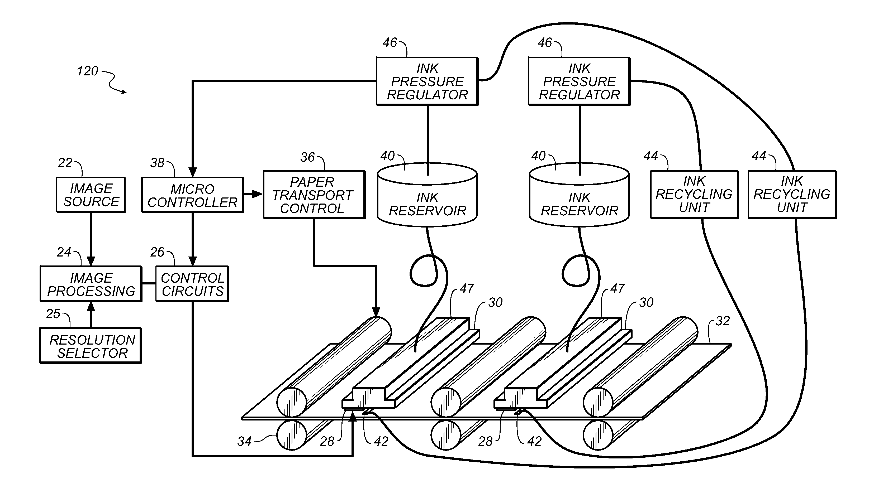
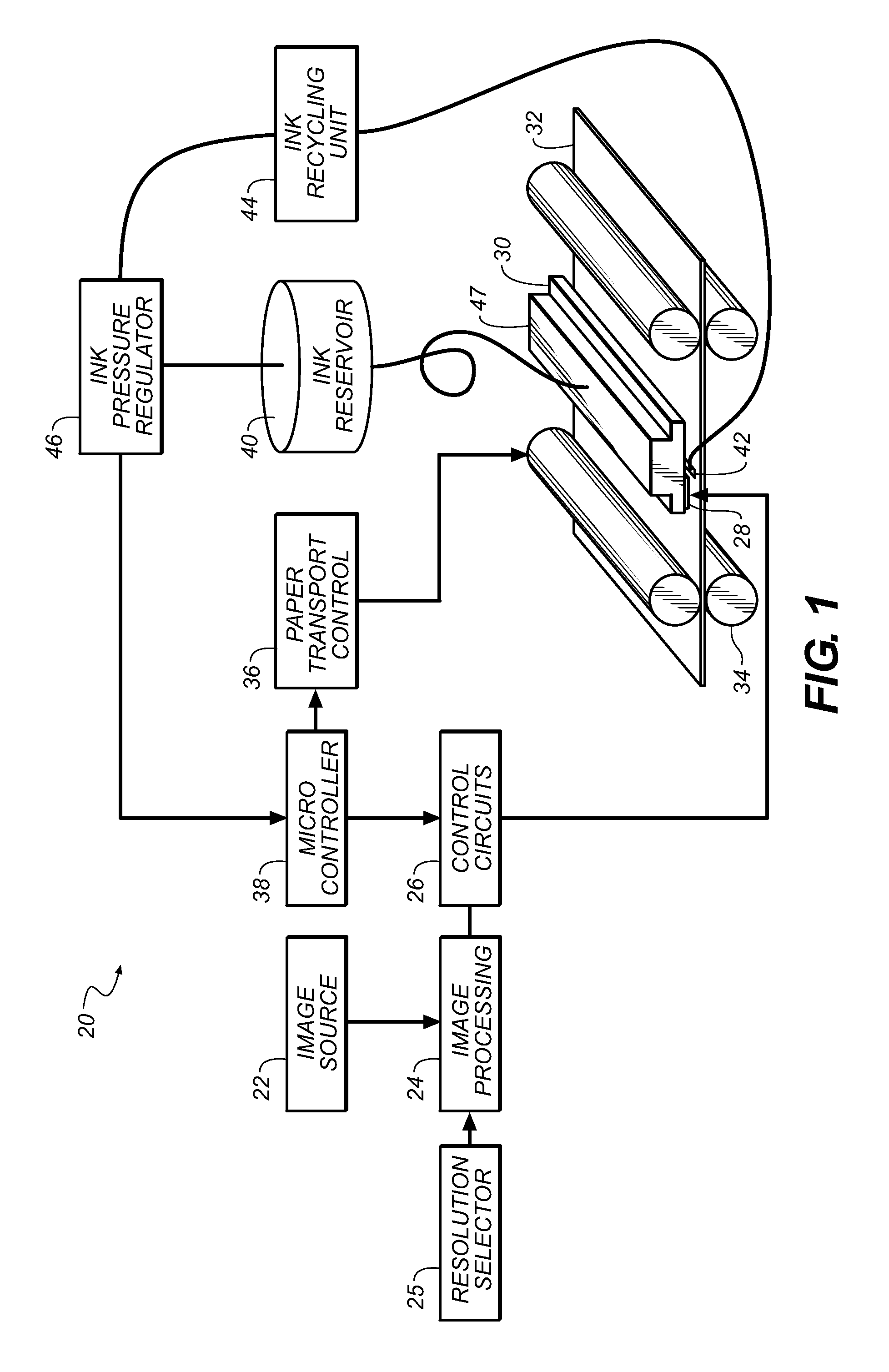
[0012]It is an advantage of the present invention that it provides an apparatus capable of printing images having different resolutions within a single system. The apparatus and method of the present invention allows the user to select predetermined resolutions and print speed combinations that were not previously achievable with a single continuous ink jet system, providing the user greater print job flexibility and lower overall equipment costs.

Problems solved by technology

Drop-on-demand drop emitter systems are limited in the drop repetition frequency that is sustainable from an individual nozzle.
However, a drop frequency maximum of 50 KHz limits the usefulness of drop-on-demand emitters for high quality patterned layer deposition to process speeds below ˜0.5 msec.
As a result, the print quality is reduced not only by the resolution reduction, but also by the lower ink coverage.
With this approach to multiple resolution printing, there is no flexibility for ink media selection, and it would be difficult to make quality prints at multiple resolutions on a single media type.
However, as a DOD technology it is fundamentally limited in the frequency at which drops can be made, thereby limiting the attainable process speeds.
The disclosure is related to gray level printing, and does not address the problems associated with using drops of mV0 increments in a multiple resolution continuous printing system.

Method used


Image

  • Multiple resolution continuous ink jet system
  • Multiple resolution continuous ink jet system
  • Multiple resolution continuous ink jet system

Examples


example 1

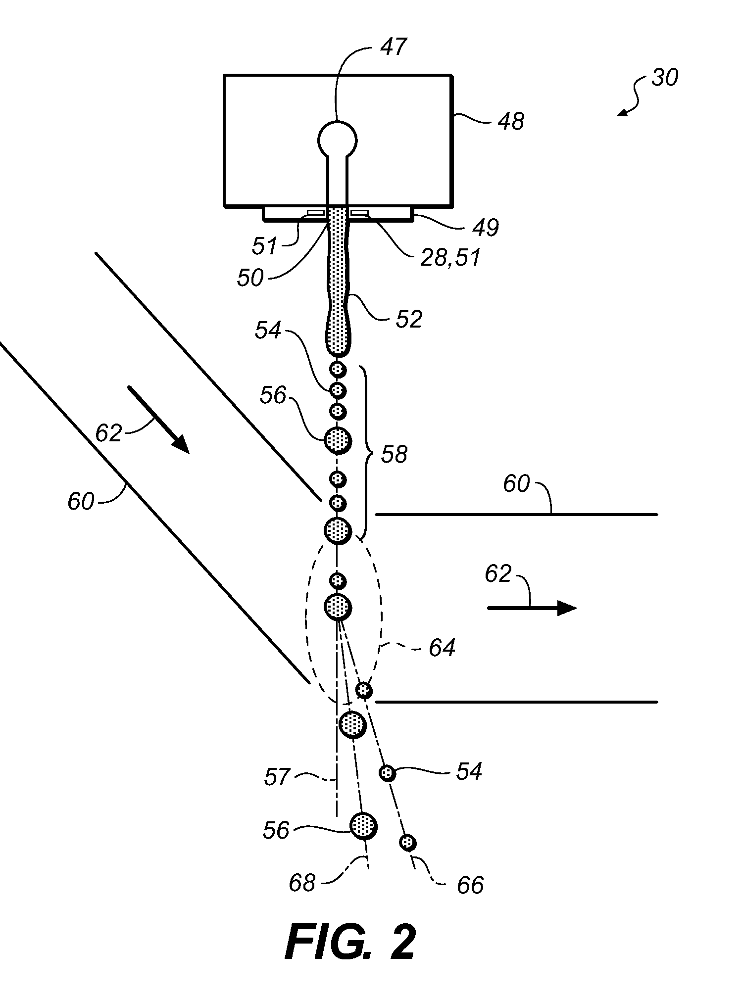
[0070]In this example a series of prints were made on glossy paper using a 600 npi printhead at resolutions of 600×900, 600×1200 and 600×2400. The printhead used in this example had a nominal nozzle diameter D0 of 8 microns, and was operated at a nominal jet velocity of 20 m / s. The frequency for forming the fundamental drop V0 was 451 kHz, resulting in a value of L of 5.7 and a drop volume V0 of 2.3 pL. Quality images were obtained with equivalent 100% fill at all three resolutions. The drop volumes used to image the three resolutions of 600×900 dpi, 600×1200 dpi and 600×2400 dpi were produced at values of m of 4, 3 and 2 respectively. Where Rscan=1200, A=2 and when Rscan=2400, A=4 consistent with the previous discussion, the Dspot-A was set to be equivalent to the Dspot for the Rarray×Rarray image of 600×600 dpi. In this example the operation conditions of the deflection mechanism were different for each printed resolution. Table 1 summarizes the results from Example 1.

TABLE 1Print...

example 2

[0071]The multiple resolution continuous printing system of Example 2 is similar to that of Example 1, except that the operating parameters of the deflection mechanism were kept the same for each of the print resolutions. The quality of the images and the values for the fill spot diameter were equivalent to Example 1. The deflection control mechanism was run at a negative air flow of 1050 and a positive air flow of 1650 for the same three resolutions as Example 1. In this example, the operating parameter values are kept the same for each of the selectable predetermined print resolutions. In both the first and second examples, the same jet velocity, vj0, is employed for each of the selectable predetermined print resolutions.

theoretical example 1

[0072]Table 1 contains details for four model multiple resolution continuous ink jet systems, A-D. All four systems A-D are designed to operated at an optimal wave ratio for the fundamental drop of L=4.5, and with a common jet velocity vj0. The systems of Table 1 are intended to be operated in single pass mode, where each color is addressed by a single array of nozzles. These four system models each provide three or four selectable predetermined print resolutions each of which has a corresponding print drop volume mV0 with a distinct value of the print drop ratio m, with the values of the print drop ratio m are integers that are greater than 1 and less than 7. As can be seen in Table 2, the print resolutions have asymmetry ratios A=Rscan / Rarray of 1, 1.5, 2, 3, and 4. That is, the predetermined print resolutions have asymmetry ratios A, where A is 1.5 or an integer greater than or equal to 1.

TABLE 2Example systems for single pass printingMAX%TargetPredictedPaperDifferenceDPIDPIDspot...


PUM


Abstract

A continuous ink jet printing system capable of printing at multiple predetermined print resolutions. The system comprises a drop generator having an array of nozzles for emitting a plurality of continuous streams of liquid for applying ink to media driven in a media advance direction having a source for pressurized liquid for supplying pressurized liquid to the plurality of nozzles. The plurality of nozzles have effective nozzle diameters D0 and a stimulation device associated with each nozzle of the plurality of nozzles for forming ink drops having predetermined drop volumes from the continuous streams of liquid. The predetermined drop volumes include non-print drops of a unit volume V0, and print drops having volumes that are integer multiples of the unit volume, mV0, wherein m is an integer greater than 1. A catcher collects the non-print drops and a selector selects a predetermined print resolution. Each predetermined print resolution has a corresponding print drop volume mV0.

Description

FIELD OF THE INVENTION[0001]This invention relates generally to the field of digitally controlled printing devices, and in particular to continuous ink jet systems capable of printing at multiple resolutions.BACKGROUND OF THE INVENTION[0002]Ink jet printing has become recognized as a prominent contender in the digitally controlled, electronic printing arena because of its non-impact, low-noise characteristics, its use of plain paper, and its avoidance of toner transfer and fixing. Other applications, requiring very precise, non-contact liquid pattern deposition, may be served by drop emitters having similar characteristics to very high resolution ink jet printheads. By very high resolution liquid layer patterns, it is meant, herein, patterns formed of pattern cells (pixels) having spatial densities of at least 300 per inch in two dimensions. Ink jet printing mechanisms can be categorized by technology as either drop-on-demand ink jet or continuous ink jet. The first technology, “dro...

Claims


Application Information

Patent Timeline
IPC IPC(8): B41J2/02
CPCB41J2/03B41J2/5056B41J2002/022B41J2202/16B41J2002/032B41J2002/033B41J2002/031
Inventor ELLINGER, CAROLYN R.
Owner EASTMAN KODAK CO
Learn More