Distortion suppression in high-level capable audio amplification circuit

Active Publication Date: 2012-05-17
INVENSENSE
View PDF0 Cites 69 Cited by
  • Summary
  • Abstract
  • Description
  • Claims
  • Application Information

AI Technical Summary

Benefits of technology

[0029]In another preferred embodiment of the audio amplification circuit, a gain or amplification of the small signal transfer function of the first preamplifier is controlled by a capacitor ratio and/or a gain or amplification of the small signal transfer function of the second preamplifier is controlled by a capacitor ratio. In the present context, the gain or amplification means the audio frequency gain or amplification. The gain or amplification is preferably defined at 1 kHz. In one such embodiment, the audio frequency gain of each of the first and second preamplifiers is controlled by a capacitance ratio between a feedback capacitor coupled between the preamplifier output and an inverting input thereof. An input capacitor is coupled from the audio input to the inverting input of the first preamplifier. The audio frequency amplification of second preamplifier is preferably controlled in a corresponding manner by another capacitance ratio which may be identical to the capacitance ratio of the first preamplifier. These gain controlling capacitors are preferably all pF-sized capacitors, e.g. each having a capacitance smaller than 500 pF. Each of the capacitors may comprise a poly-poly capacitor or a MIM capacitor to achieve accurate setting of the respective gains of first and second preamplifiers. In addition, the use o

Problems solved by technology

At such large audio input signal levels, the input signal to first preamplifier is severely distorted due to the non-linearity of the the non-linear element.
Unfortunately, a portion of the distorted audio input signal at the first preamplifier is coupled to the second preamplifier by an unintended or parasitic signal path extending through the attenuator.
This unintended transmission of signal distortion through the parasitic path is basically caused by the extremely large impedance level of the capacitive transducer element of the miniature ECM or MEMS condenser microphone which prevents the capacitive transducer element in effectively co

Method used


Image

  • Distortion suppression in high-level capable audio amplification circuit
  • Distortion suppression in high-level capable audio amplification circuit
  • Distortion suppression in high-level capable audio amplification circuit

Examples


Embodiment Construction

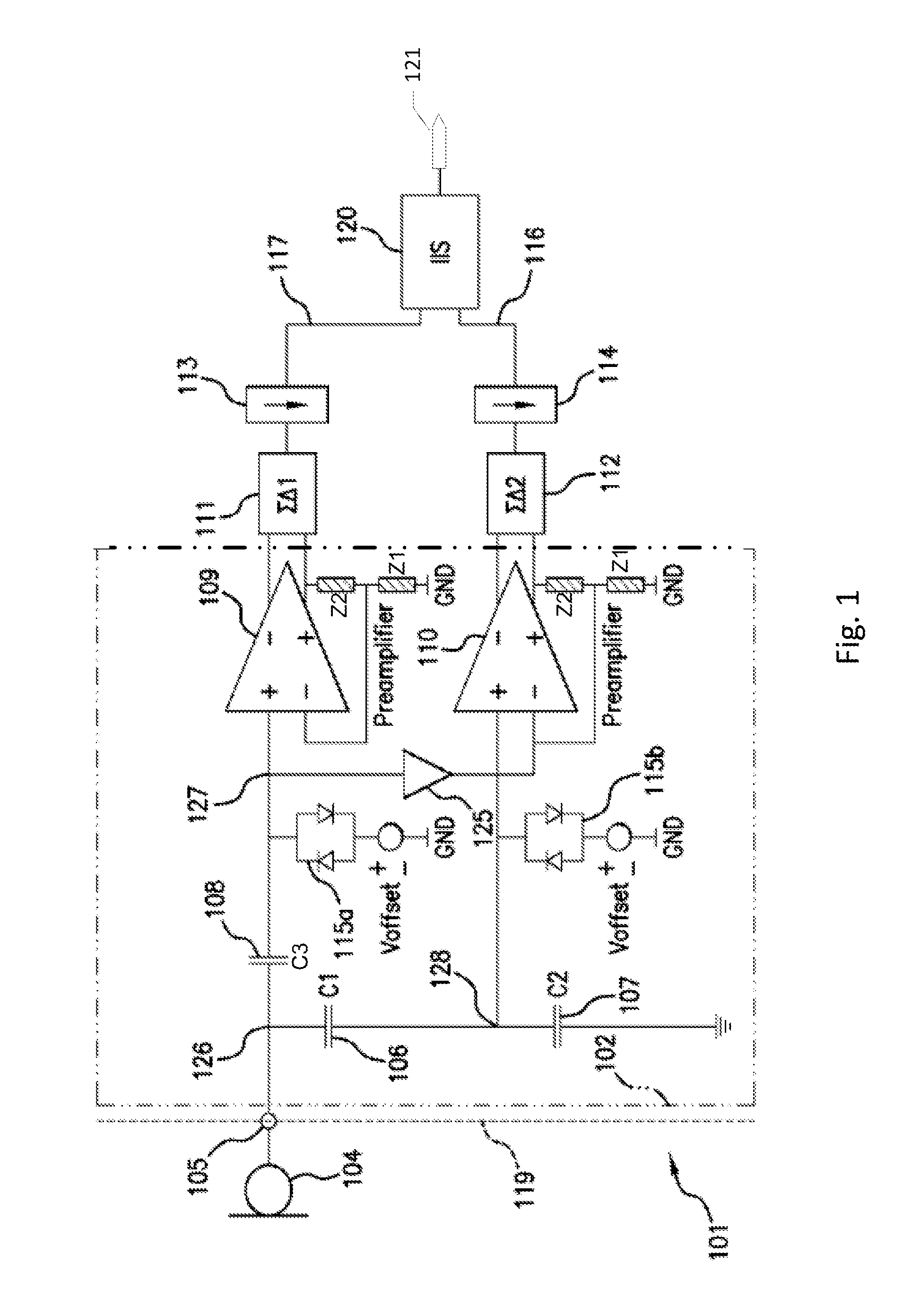
[0045]FIG. 1 is a schematic drawing of an audio amplification system 101 which comprises a microphone 104 operatively coupled to an audio amplification circuit 102 according to a first embodiment thereof. The audio amplification system 101 may serve as amplifying and digitizing front-end of a subsequent DSP based audio signal processing circuit (not shown). The audio amplification circuit 102 is configured to supply first and second analog output signals with different input referred overload points to enhance the dynamic range handling capability of the audio amplification system 101. The audio amplification circuit 102 may either be fabricated or implemented on separate CMOS semiconductor die or it may be fabricated on a CMOS semiconductor die together with first and second analogue-to-digital converters 111, 112 coupled to a digital audio interface 120. A separate DSP based audio signal processing circuit may reside remotely for example within a portable terminal in form of an ap...


PUM


Abstract

The present invention relates to an audio amplification circuit comprising a first preamplifier for receipt of an audio input signal and a second preamplifier comprising a first differential input for receipt of an attenuated audio input signal. The attenuated audio input signal is generated by an attenuator coupled to the audio input signal. A non-linear element is coupled to a first input of the first preamplifier thereby distorting the audio input signal at the first input at large signal levels. A distortion compensation network is adapted to supply a distortion compensation signal from the first input of the first preamplifier to a second differential input of the second preamplifier such that distortion in the output signal of the second preamplifier is cancelled or attenuated. The invention further relates to a corresponding method of compensating an audio amplification circuit for distortion induced by a non-linear element.

Description

[0001]The present invention relates to an audio amplification circuit comprising a first preamplifier for receipt of an audio input signal and a second preamplifier comprising a first differential input for receipt of an attenuated audio input signal. The attenuated audio input signal is generated by an attenuator coupled to the audio input signal. A non-linear element is coupled to a first input of the first preamplifier thereby distorting the audio input signal at the first input at large signal levels. A distortion compensation network is adapted to supply a distortion compensation signal from the first input of the first preamplifier to a second differential input of the second preamplifier such that distortion in the output signal of the second preamplifier is cancelled or attenuated. The invention further relates to a corresponding method of compensating an audio amplification circuit for distortion induced by a non-linear element.BACKGROUND[0002]Acceptable handling of audio s...

Claims


Application Information

Patent Timeline
IPC IPC(8): H04B15/00
CPCH03F1/3211H04R19/04H03F3/45475H03F3/68H03F2200/03H03F2200/331H03F2203/45138H03F2203/45552H03F2203/45571H03F2203/45586H03G3/30H04R3/06H04R2499/11H04R19/005H03F3/187
Inventor HENRIKSEN, JENS JORGEN GAARDE
Owner INVENSENSE
Why Eureka
Try Eureka