Check patentability & draft patents in minutes with Patsnap Eureka AI!

Fuel cell cooling system of fuel cell for vehicle

Inactive Publication Date: 2012-05-17
HYUNDAI MOTOR CO LTD
View PDF5 Cites 7 Cited by
  • Summary
  • Abstract
  • Description
  • Claims
  • Application Information

AI Technical Summary

Benefits of technology

[0019]The present invention provides a fuel cell cooling system for a vehicle that reduces a temperature deviation between an inlet and an outlet of a fuel cell cooling system by forming two or more cooling water channels having a first port and a second port and allowing a fluid to flow in different directions in the two or more cooling water channels. Accordingly, the efficiency of the entire fuel cell system in accordance with the illustrative embodiment of the present invention may be decreased as the power generation efficiency of a stack becomes varied due to a temperature difference between a first section and a second section of a cooling passage generated by heat transfer of the cooling water in the stack.
[0023]In the fuel cell cooling system according to the present invention, the output (performance) and the durability of a stack are improved by reducing a temperature difference between a first section through which cooling water is introduced and a second section through which the cooling water is discharged along the flow direction of the cooling water and thus preventing local reduction of efficiency by providing two more cooling water channels formed such that the cooling water flows in different directions.

Problems solved by technology

In particular, as tens or hundreds of unit fuel cells are generally stacked in the fuel cell stack to generate an output of large capacity required for driving of the fuel cell stack, a cooling system for cooling the stack is inevitably necessary to prevent temperature increases due to the heat generated in the stack.
However, polymer electrolyte membranes melt above a certain temperature and the transfer efficiency of hydrogen is reduced due to vaporization of moisture inside, thus resulting in damage to the electrolyte membrane and a lower output.
On the other hand, the water produced in the reaction fails to be vaporized below a certain temperature of the fuel cell stack.
Thus, when this temperature is reached, an excessive amount of water is condensed to be converted into a liquid state, and thus blocks cathode channels and hampers supply of oxygen, again lowering the overall output of the system.
However, as illustrated in FIG. 2, in a conventional cooling water circulating loop, temperature rises through the exchange of heat while the cooling water is passing through the stack, thereby causing a temperature deviation in the stack between a first section where the cooling water is introduced and a second section where the cooling water is discharged.
Accordingly, the efficiency and durability of the fuel cell is deteriorated due to a local difference in the power generating efficiency between the first section and the second section.

Method used


Image

  • Fuel cell cooling system of fuel cell for vehicle
  • Fuel cell cooling system of fuel cell for vehicle
  • Fuel cell cooling system of fuel cell for vehicle

Examples


Embodiment Construction

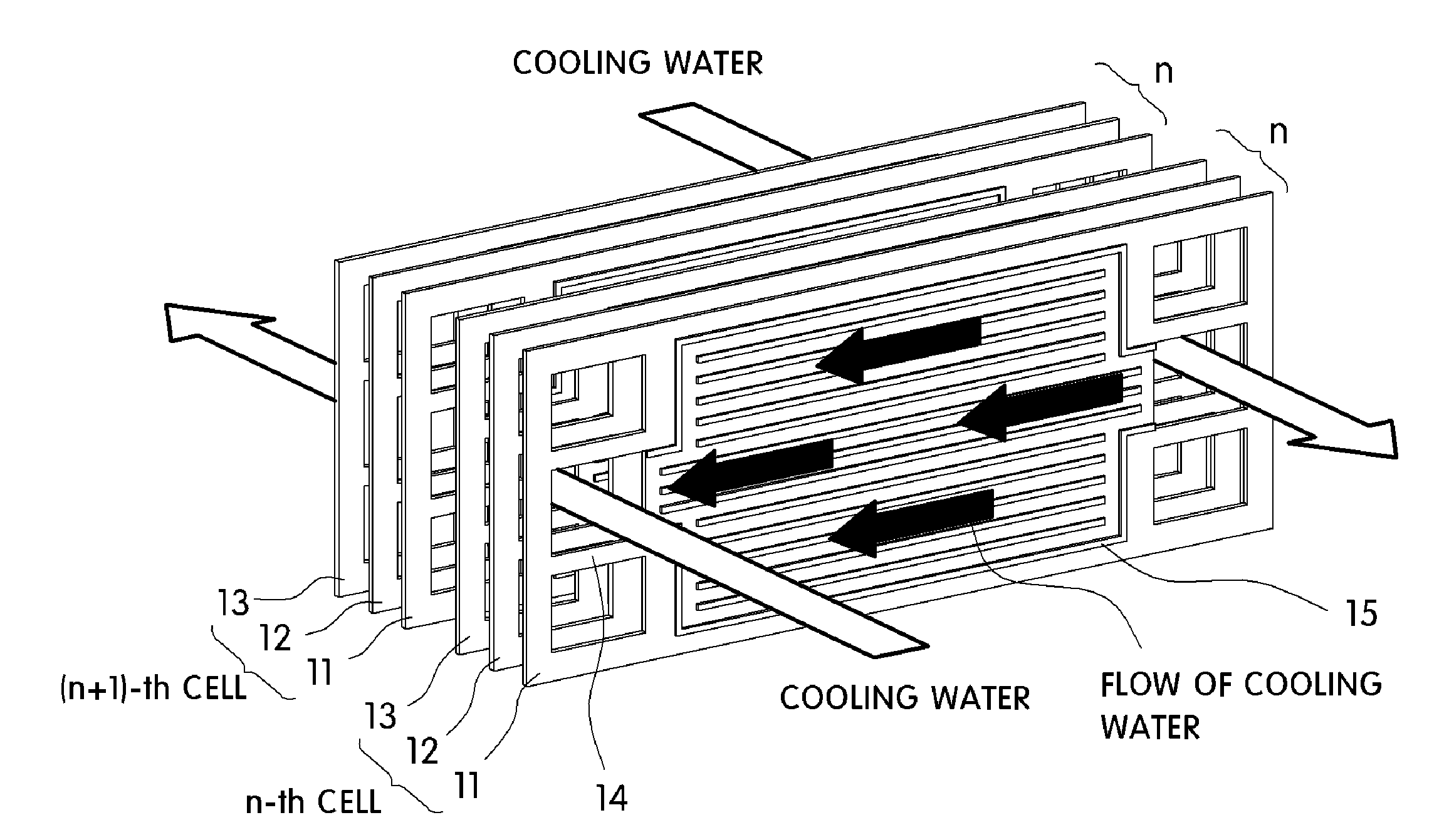
[0030]The present invention relates to a cooling system for smoothly cooling a fuel cell system applied to a fuel cell vehicle and provides a detailed structure of cooling passages that reduces a temperature deviation generated when heat of cooling water circulating in a cooling system is exchanged in a stack.

[0031]The terms in the subject application are used only to explain specific embodiments, but are not intended to limit the present invention. A singular expression includes a plural expression as long as it definitely has a specific meaning in the context. It should be understood that in the subject application, such terms as “comprise” and “include” are just intended to designate existence of a feature, a number, a step, an operation, an element, a part or a combinations thereof which are described in the specification but are not intended to exclude existence of one or more features, numbers, steps, operations, elements, parts, or combinations thereof, or any possibility of ...


PUM


Abstract

The present invention relates to a fuel cell cooling system for a vehicle comprising: a cooling water circulating loop formed to cool a fuel cell stack where a plurality of fuel cells are stacked. The cooling water circulating loop includes: a plurality of cooling water introducing ports through which cooling water passing through the stack is introduced; a plurality of cooling water discharging ports corresponding to the plurality of cooling water introducing ports and through which the cooling water which has passed through the stack is discharged; and a plurality of cooling water channels connecting the plurality of cooling introducing ports and the plurality of cooling water discharging ports. Notably, cooling water flows in different directions in the plurality of cooling water channels.

Description

CROSS-REFERENCE TO RELATED APPLICATION[0001]This application claims under 35 U.S.C. §119(a) the benefit of Korean Patent Application No. 10-2010-0112965 filed Nov. 12, 2010, the entire contents of which are incorporated herein by reference.BACKGROUND[0002](a) Technical Field[0003]The present invention relates to a fuel cell cooling system for a vehicle. More particularly, the present invention relates to a fuel cell cooling system for a vehicle that efficiently cools heat generated in the process of producing electric energy in a fuel cell for a vehicle.[0004](b) Background Art[0005]A fuel cell is a type of power generating apparatus that converts chemical energy contained in a fuel to electric energy by electrochemically reacting the fuel within a fuel cell stack without burning the fuel into heat. Fuel cells not only supply electric power for industry, homes, and vehicles but may also be applied to small-sized electric / electronic products, especially to supply of power to portable...

Claims


Application Information

Patent Timeline
IPC IPC(8): H01M8/04
CPCH01M8/0267H01M8/04029Y02T90/32H01M2250/20Y02E60/50H01M8/241Y02T90/40H01M8/2483H01M8/04F25D17/00B60L50/50H01M8/0258
Inventor NAM, GI YOUNGKIM, CHI MYUNGKO, HAEONG JINKIM, SEONG KYUNLEE, SEUNG YONGKIM, YUN SEOK
Owner HYUNDAI MOTOR CO LTD
Features
  • R&D
  • Intellectual Property
  • Life Sciences
  • Materials
  • Tech Scout
  • Unparalleled Data Quality
  • Higher Quality Content
  • 60% Fewer Hallucinations
Learn More