Methods for interconnecting photovoltaic cells

a photovoltaic cell and interconnection technology, applied in the direction of photovoltaics, electrical equipment, semiconductor devices, etc., can solve the problem of greater shorting potential in the interconnection circui

Inactive Publication Date: 2012-05-24
SOLOPOWER
View PDF0 Cites 181 Cited by
  • Summary
  • Abstract
  • Description
  • Claims
  • Application Information

AI Technical Summary

Benefits of technology

[0013]The aforementioned needs are satisfied by the present invention which, in one implementation comprises a method of serially interconnecting first and second solar cells in a shingled manner, wherein each solar cell includes an absorber layer interposed between a conductive substrate and a transparent layer having a top surface on which a conductive terminal including conductive fingers connected to a current collecting busbar is disposed. In this implementation, the method comprises forming at least one contact on the current collecting busbar disposed over an edge portion of the first solar cell; disposing an electrically insulating layer over the current collecting busbar and at least a portion of the top surface of the transparent layer, the electrically insulating layer at least partially exposing the at least one contact. In this implementation, the method further comprises arranging the first and second cells in a shingled relationship so as to connect a selected area of a portion of the conductive substrate of the second solar cell to the at least one contact on the conductive terminal of the first solar cell to establish continuous electrical connection between the terminal of the first solar cell and the substrate of the second solar cell while the portion of the conductive substrate of the second cell is resting on the electrically insulating layer that is at least partially exposi

Problems solved by technology

However, without any dielectric material protection between the cells, various components of the interconnected cells may touch one another resulting in greater potential of shorting in the interconnected circuit.
This is, for example, a particular problem in flexible solar modules using thin film solar cells as the substrate of the upper solar cell can penetrate into the absorber layer and contact the substrate of the bottom solar cell when the flexible module is placed under stress due to bending.

Method used


Image

  • Methods for interconnecting photovoltaic cells
  • Methods for interconnecting photovoltaic cells
  • Methods for interconnecting photovoltaic cells

Examples


Embodiment Construction

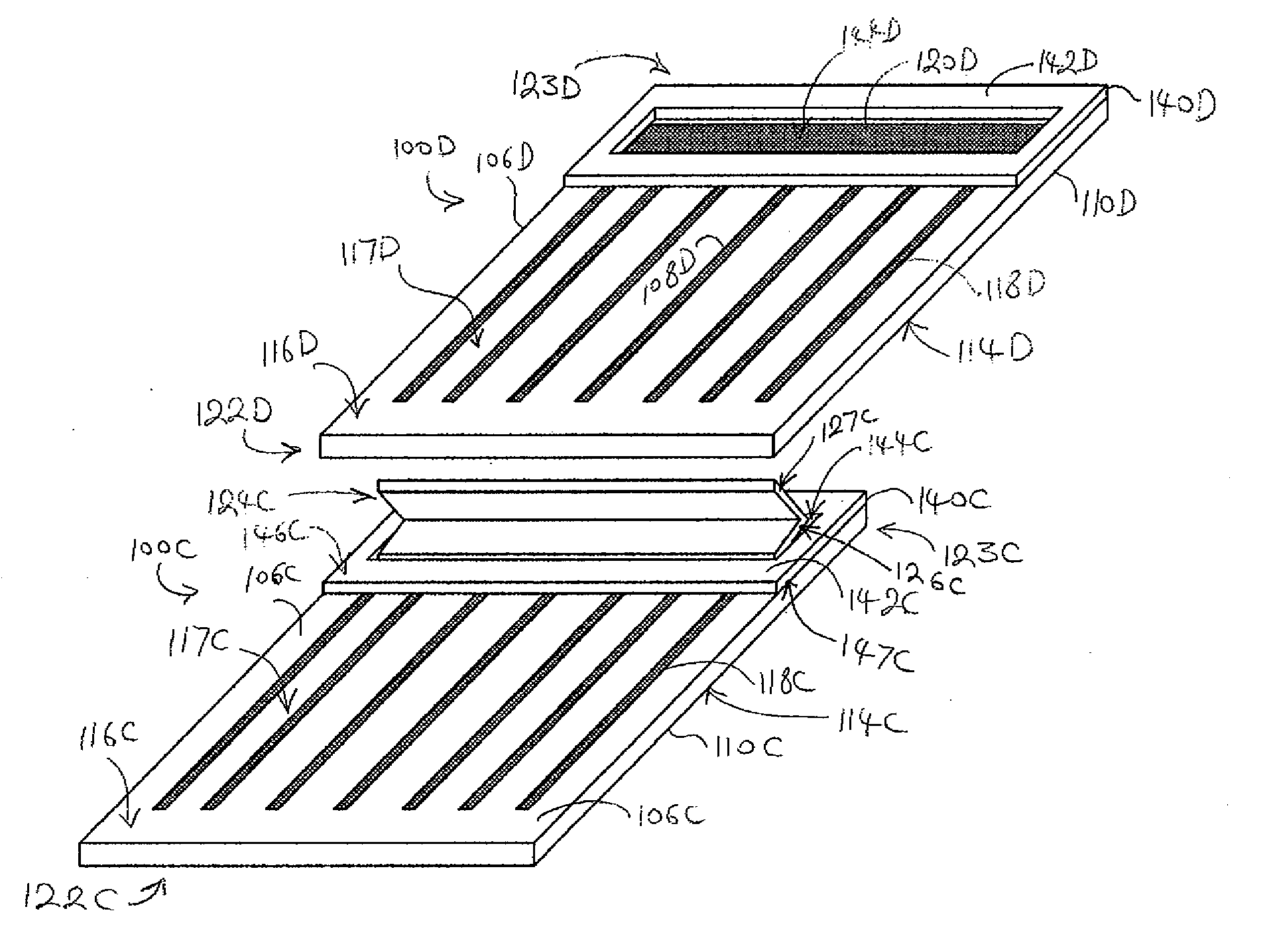
[0025]The preferred embodiments described herein provide methods of interconnecting solar cells or photovoltaic cells. In one embodiment, the solar cells, for example a first and second solar cells, may be interconnected in series in a manner referred to as a shingled relationship such that a substrate portion of the second solar cell overlaps with a surface portion of the first solar cell.

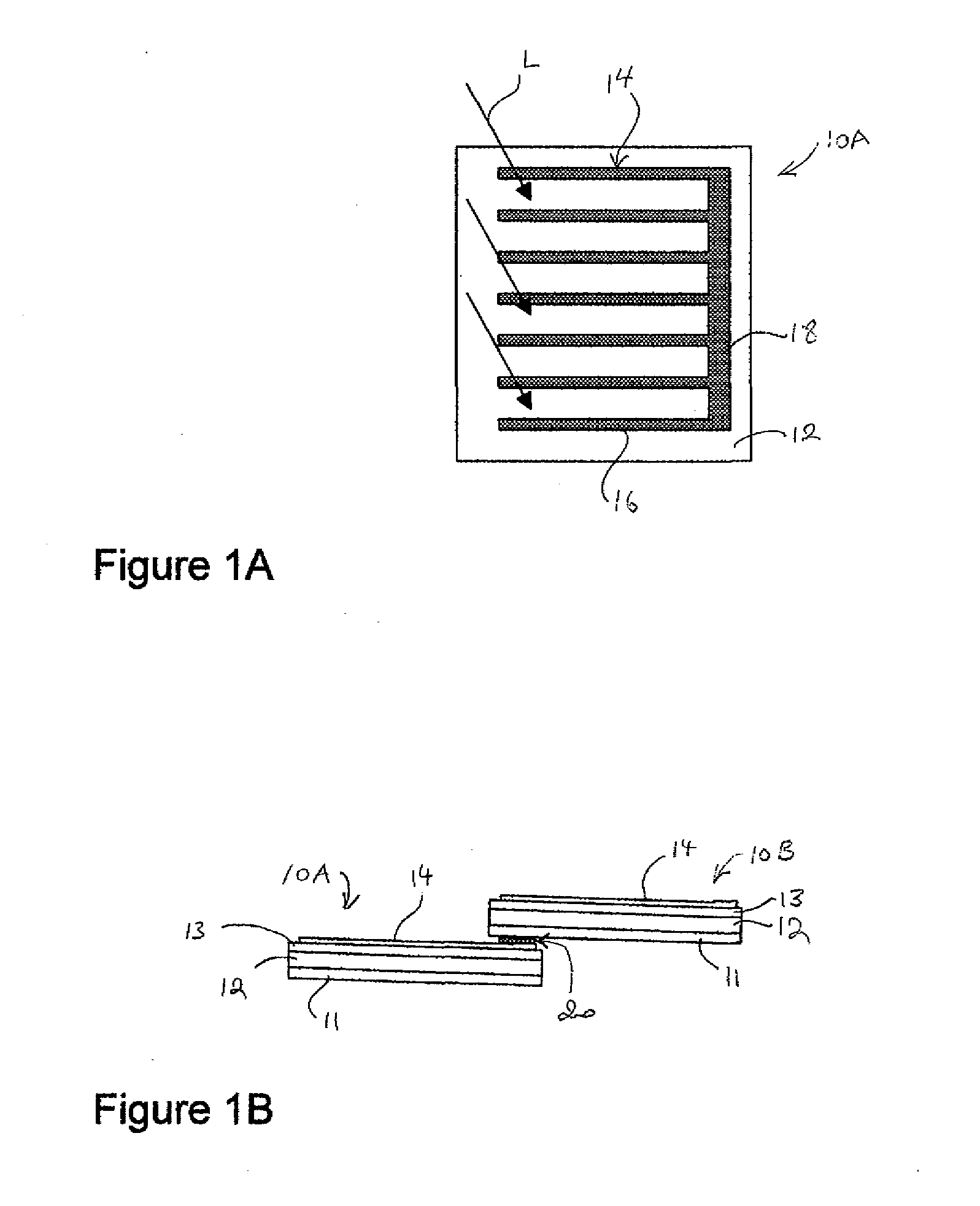
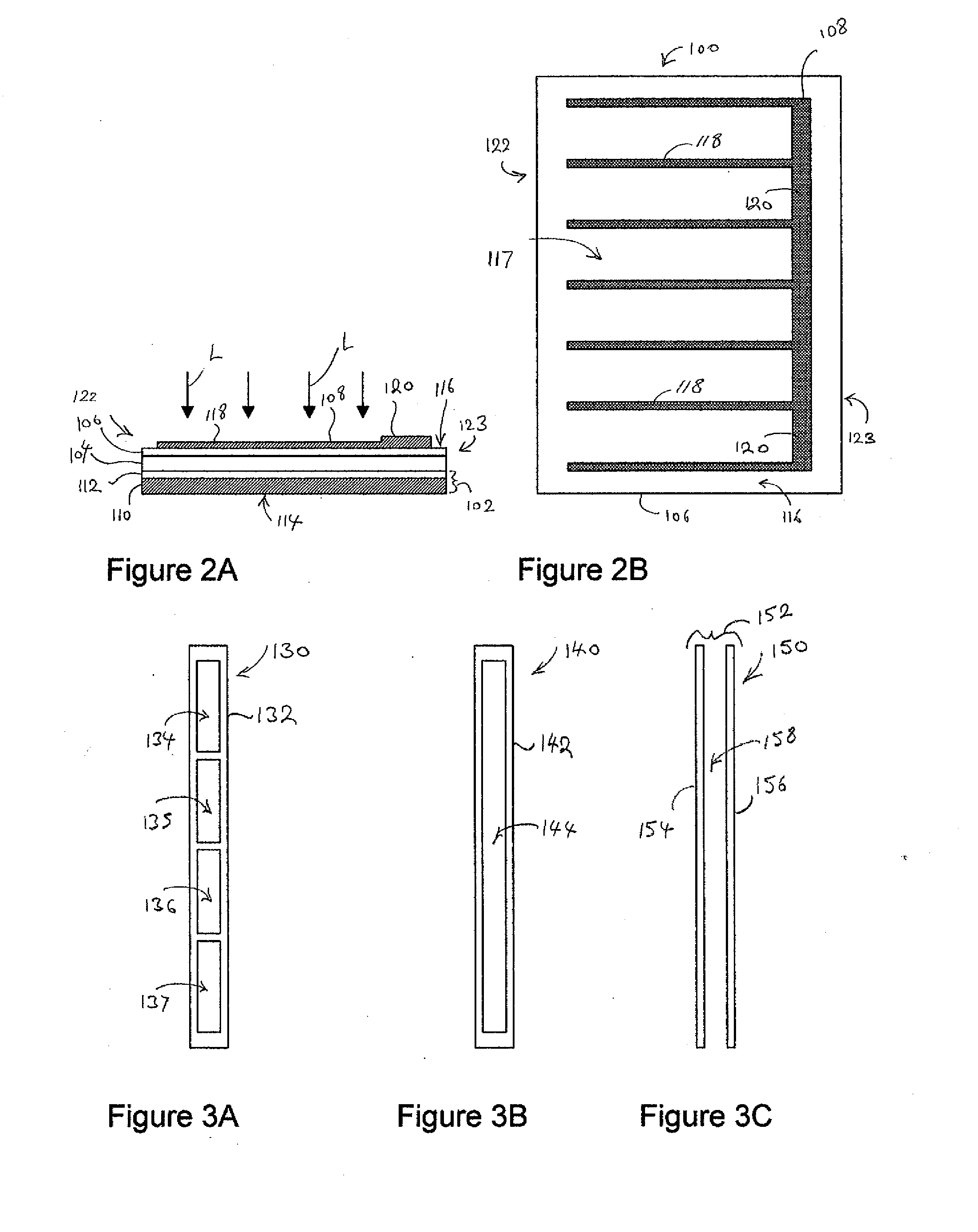
[0026]In one embodiment, each interconnected solar cell includes a thin film absorber layer interposed between a conductive substrate and a transparent layer, the thin film absorber layer having a top surface on which a conductive terminal including conductive fingers connected to a current collecting busbar is disposed. The solar cells may be interconnected using a contact formed on the current collecting busbar that is located at an edge portion of the first solar cell. An insulation layer may be disposed over the terminal and the top surface of the transparent layer of the first solar cell. The...


PUM


Abstract

Two or more solar cells are shingled together. At least one solar cell has a contact formed on a first surface that is electrically connected to the conductive terminal of the solar cell. A substrate of a second cell is physically and electrically coupled to the contact. An insulator is interposed between the substrate of the second cell and the first cell to inhibit short circuits therebetween.

Description

BACKGROUND[0001]1. Field of the Inventions[0002]The present inventions generally relate to apparatus and methods of solar module design and fabrication and, more particularly, to interconnecting solar cells.[0003]2. Description of the Related Art[0004]Solar cells are photovoltaic (PV) devices that convert sunlight directly into electrical energy. Solar cells can be based on crystalline silicon or thin films of various semiconductor materials that are usually deposited on low-cost substrates, such as glass, plastic, or stainless steel.[0005]Thin film based photovoltaic cells, such as amorphous silicon, cadmium telluride, copper indium diselenide or copper indium gallium diselenide based solar cells, offer improved cost advantages by employing deposition techniques widely used in the thin film industry. Group IBIIIAVIA compound photovoltaic cells, including copper indium gallium diselenide (CIGS) based solar cells, have demonstrated the greatest potential for high performance, high ef...

Claims


Application Information

Patent Timeline
IPC IPC(8): H01L31/05H01L31/18
CPCY02E10/50H01L31/0504
Inventor PINARBASI, MUSTAFALEE, ERICERDEMLI, SERKANPETRUSHANSKY, EUGENE
Owner SOLOPOWER
Why Eureka
Try Eureka