Cylindrical Surface Spin Weld Apparatus and Method of Use

a spin welding and cylindrical surface technology, applied in the direction of coupling device connection, application, other domestic objects, etc., can solve the problems of oversized finished products and increased manufacturing costs

Active Publication Date: 2012-05-24
COMMSCOPE TECH LLC
View PDF3 Cites 11 Cited by
  • Summary
  • Abstract
  • Description
  • Claims
  • Application Information

AI Technical Summary

Benefits of technology

[0028]The inventor has further recognized that molten material may be contained during the spin welding process by enclosing at least one of the objects within a longitudinally enclosing drive collet. Thereby, spin welding along mating cylindrical surfaces with a significant longitudinal extent coaxial with the axis of rotation and / or simultaneously between different material mating surface pairs having different melt characteristics may be performed with reduced chance of generating an unacceptable spin weld quality.
[0031]As best shown in FIG. 4, the spin weld apparatus 2 may be provided with a stop 24 for stopping a prepared end 4 of the coaxial cable 6 at a predefined longitudinal extension from the end of the cable clamp 10. The stop 24 may be provided with a pivot end 26 pivotally coupled with the cable clamp base 18 and an attachment end 28 interlockable with the cable clamp base 18, for example via insertion into a slot 30 of the base 18. The stop 24 is dimensioned to stop the coaxial cable 6 at a predefined longitudinal position within the clamp 10 such that the prepared end 4 is located at a known position with respect to the spin welder 36 (see FIG. 8). Thereby, a known longitudinal extension of the spin welder 36 towards the cable clamp 10 will generate a repeatable spin welding result. An actuator 22 operable to pivot the stop 24 with respect to the cable clamp base 18 may be coupled with the stop 24 to provide quick insertion and removal of the stop 24 so that each coaxial cable 6 may be quickly and repeatably inserted into the same longitudinal position within the cable clamp 10. Alternatively, the stop 24 may be arranged to move, for example, vertically or horizontally in and out of the desired prepared end 4 abutting position or a spaced away position allowing the approach of the spin welder 16 to the prepared end 4.
[0036]As best shown in FIG. 10, an end of the drive collet 32 facing the cable clamp 10, when the spin welder 36 is longitudinally aligned with the prepared end 4 of the coaxial cable 6, may be provided with a collet flange 58 extending radially inward short of contacting the coaxial cable 6 to further assist with the retention of softened and / or molten material within the drive collet 32 resulting from spin welding.
[0045]Because the radial inward displacement of the wedge portion(s) 68 may be actuated independently of the spin welder longitudinal position and / or a longitudinal force level thereagainst, the possibility of crush damage to the prepared end 4 of the coaxial cable 6 may be reduced.
[0046]One skilled in the art will appreciate that the invention may provide a cost efficient method and apparatus for increased quality of spin welds, especially where a cylindrical spin weld along a cylindrical surface with a significant longitudinal extent is desired. Further, the invention may improve spin weld result for simultaneous spin welding between material pairs with different material characteristics. When spin welding is performed along an extended cylindrical friction surface 8 and / or simultaneously performed between both polymer and metal mating surface pairs, the polymer surfaces are likely to reach a softening / melting point before the metal surfaces, increasing the likelihood that overheating between mating surfaces will occur. An overheated material may begin to further distort radially outward under the influence of centrifugal force. By the present invention, the dimensions and integrity of the cylindrical friction surface 8 are reinforced, reducing the likelihood of the softened polymer surfaces separating and / or deforming under the influence of centrifugal force.Table of Parts2coaxial connector4prepared end6coaxial cable8friction surface9overbody10cable clamp11outer jacket12outer conductor13connector body14top cable clamp portion16bottom cable clamp portion18cable clamp base20hinge22actuator24stop26pivot end28attachment end30slot32drive collet34interlocking portion36spin welder38spindle socket40spindle42first collet portion44second collet portion46interlock slot48support ridge50spring detent screws52spring detent screw aperture54ball bearing56detent groove58collet flange60cam62pivot pin64drive plate66drive pin68wedge portion69wedge slot70retaining arm72spring

Problems solved by technology

However, oversized object dimensions require additional material, increasing the cost of manufacture and resulting in a finished product with oversized dimensions.

Method used


Image

  • Cylindrical Surface Spin Weld Apparatus and Method of Use
  • Cylindrical Surface Spin Weld Apparatus and Method of Use
  • Cylindrical Surface Spin Weld Apparatus and Method of Use

Examples


Embodiment Construction

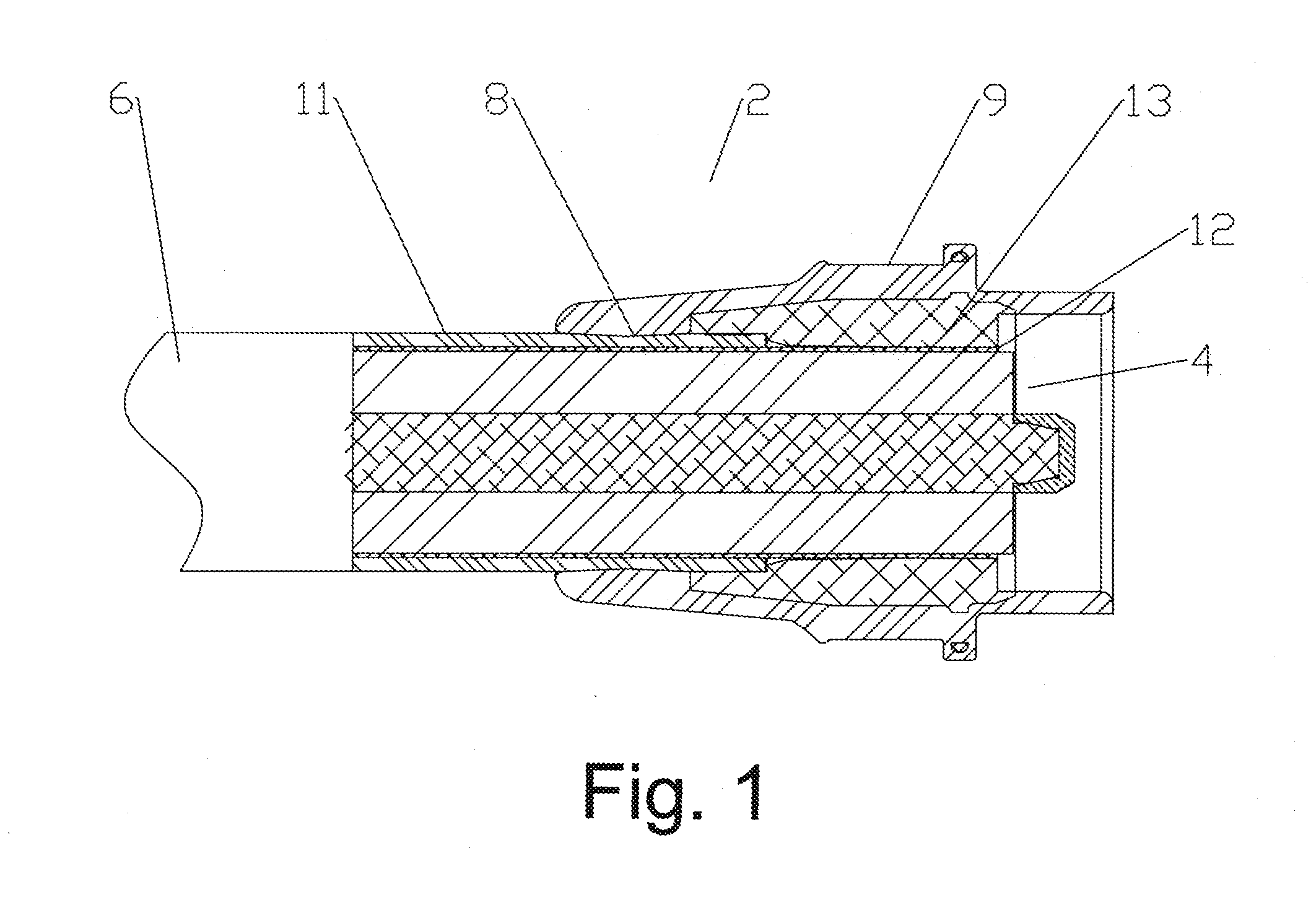
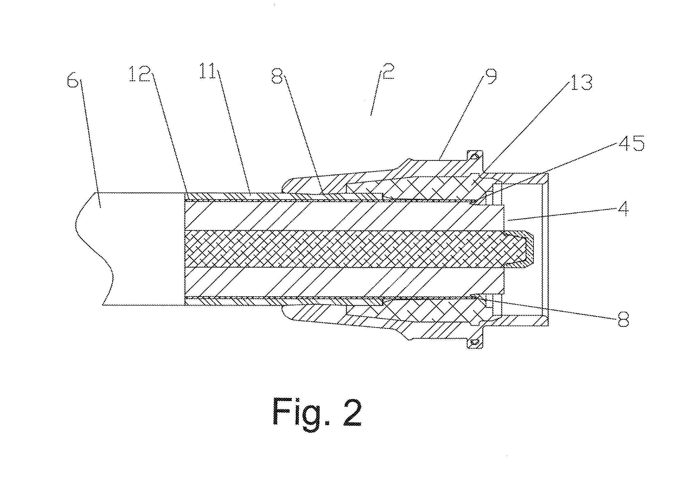
[0025]Coaxial cables for the transmission of radio frequency signals are terminated with coaxial connectors for ease of interconnection with further coaxial cables and / or other equipment. These coaxial connectors may be coupled to the prepared coaxial cable end in part or entirely via spin welding. As shown for example in FIG. 1, a coaxial connector 2 generally as disclosed in U.S. patent application Ser. No. 12 / 951,558, filed Nov. 22, 2010, may be dimensioned for interconnection with a prepared end 4 of a coaxial cable 6 via a combination of spin welding and laser welding. For spin welding, a polymer material overbody 9 may be provided with a cylindrical friction surface 8 along an inner diameter of the coaxial connector 2 for spin welding with the outer diameter of a polymer outer jacket 11 of the coaxial cable 6. After spin welding, the metal outer conductor 12 of the coaxial cable 6 may be laser welded to the metal connector body 13, at the connector end, in a separate manufactu...


PUM

PropertyMeasurementUnit
displacementaaaaaaaaaa
longitudinal displacementaaaaaaaaaa
outer diameteraaaaaaaaaa

Abstract

A spin weld apparatus for spin welding a prepared end of a coaxial cable with a coaxial connector includes a cable clamp dimensioned to grip the coaxial cable and a drive collet dimensioned to enclose and rotationally interlock with a lateral surface of the coaxial connector. The drive collet is dimensioned to rotationally interlock with an interlocking portion of a spin welder. The spin welder is dimensioned to axially align the coaxial connector with the coaxial cable for spin welding when the drive collet is rotationally interlocked with the spin welder.

Description

CROSS REFERENCE TO RELATED APPLICATIONS[0001]This application is a continuation-in-part of commonly owned co-pending U.S. Utility patent application Ser. No. 12 / 962,943, titled “Friction Weld Coaxial Connector and Interconnection Method”, filed Dec. 8, 2010 by Kendrick Van Swearingen, currently pending and hereby incorporated in its entirety, which is a continuation-in-part of commonly owned co-pending U.S. patent application Ser. No. 12 / 951,558, titled “Laser Weld Coaxial Connector and Interconnection Method”, filed Nov. 22, 2010 by Ronald A. Vaccaro, Kendrick Van Swearingen, James P. Fleming, James J. Wlos and Nahid Islam, currently pending and hereby incorporated by reference in its entirety.BACKGROUND[0002]1. Field of the Invention[0003]This invention relates to a spin welding apparatus. More particularly, the invention relates to an apparatus for spin welding between coaxial cylindrical surfaces.[0004]2. Description of Related Art[0005]Apparatus for spin welding, a type of fric...

Claims


Application Information

Patent Timeline
Patent Type & Authority Applications(United States)
IPC IPC(8): H01B13/016
CPCH01R9/05H01R24/40H01R43/02H01R2103/00B29C66/32B29C66/526B29C65/0672B29C65/069B29C65/7841B29C66/5344B29L2031/3462B29C66/1122Y10T29/53235Y10T29/53209
Inventor VAN SWEARINGEN, KENDRICK
Owner COMMSCOPE TECH LLC
Why Eureka
Try Eureka