Heat exchanger of the plate type

a technology of heat exchanger and plate, which is applied in the direction of solar heat collectors with working fluids, stationary conduit assemblies, solar heat devices, etc., can solve the problems of easy detachment of welding, plate delamination, and flat surface, and achieve the effect of increasing efficiency

Inactive Publication Date: 2012-05-24
HIFORM +1
View PDF7 Cites 21 Cited by
  • Summary
  • Abstract
  • Description
  • Claims
  • Application Information

AI Technical Summary

Benefits of technology

[0013]In an advantageous embodiment of the invention the exposed plate (2) is formed in a heat conductive material, which increases the efficiency if the heat exchanger is used e.g. as a “sunlight collector”.

Problems solved by technology

A disadvantage of the Swedish patent is that the point welding process results in a quite flat surface.
Another disadvantage is that the point weldings easily detach when the fluid is pressurized, incurring delamination of the plates.

Method used


Image

  • Heat exchanger of the plate type
  • Heat exchanger of the plate type
  • Heat exchanger of the plate type

Examples


Embodiment Construction

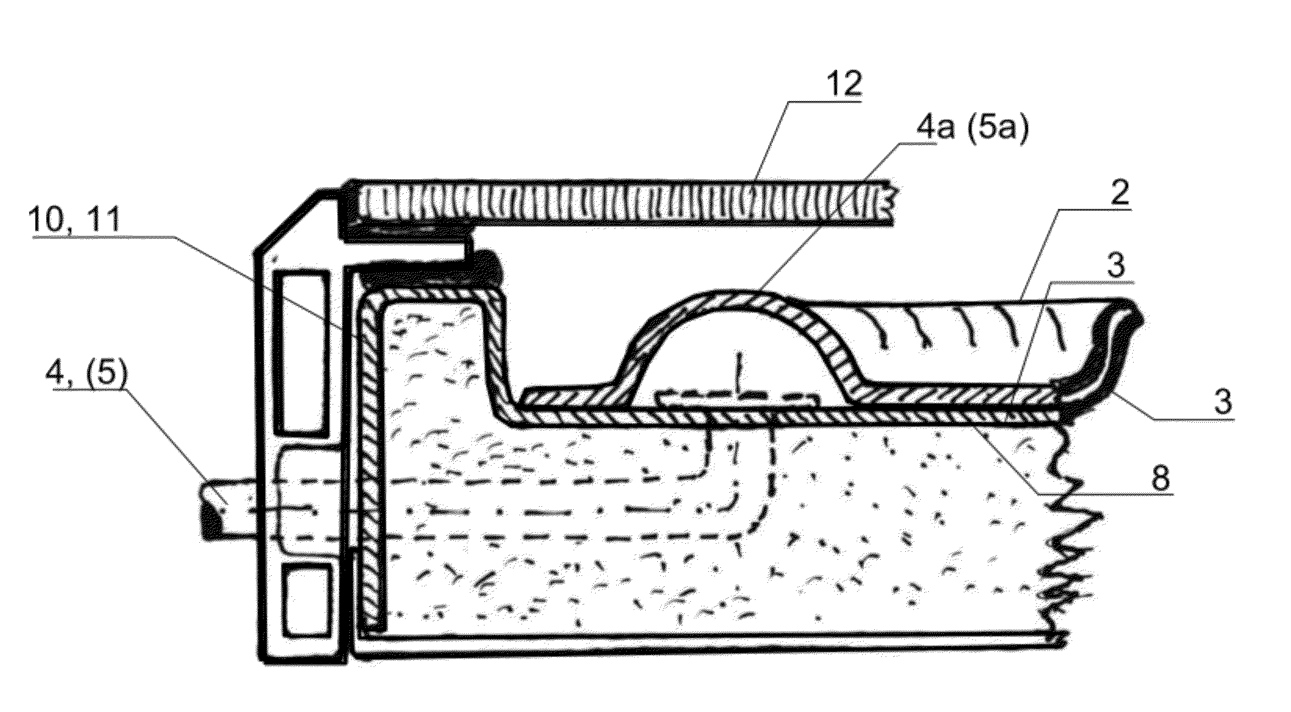
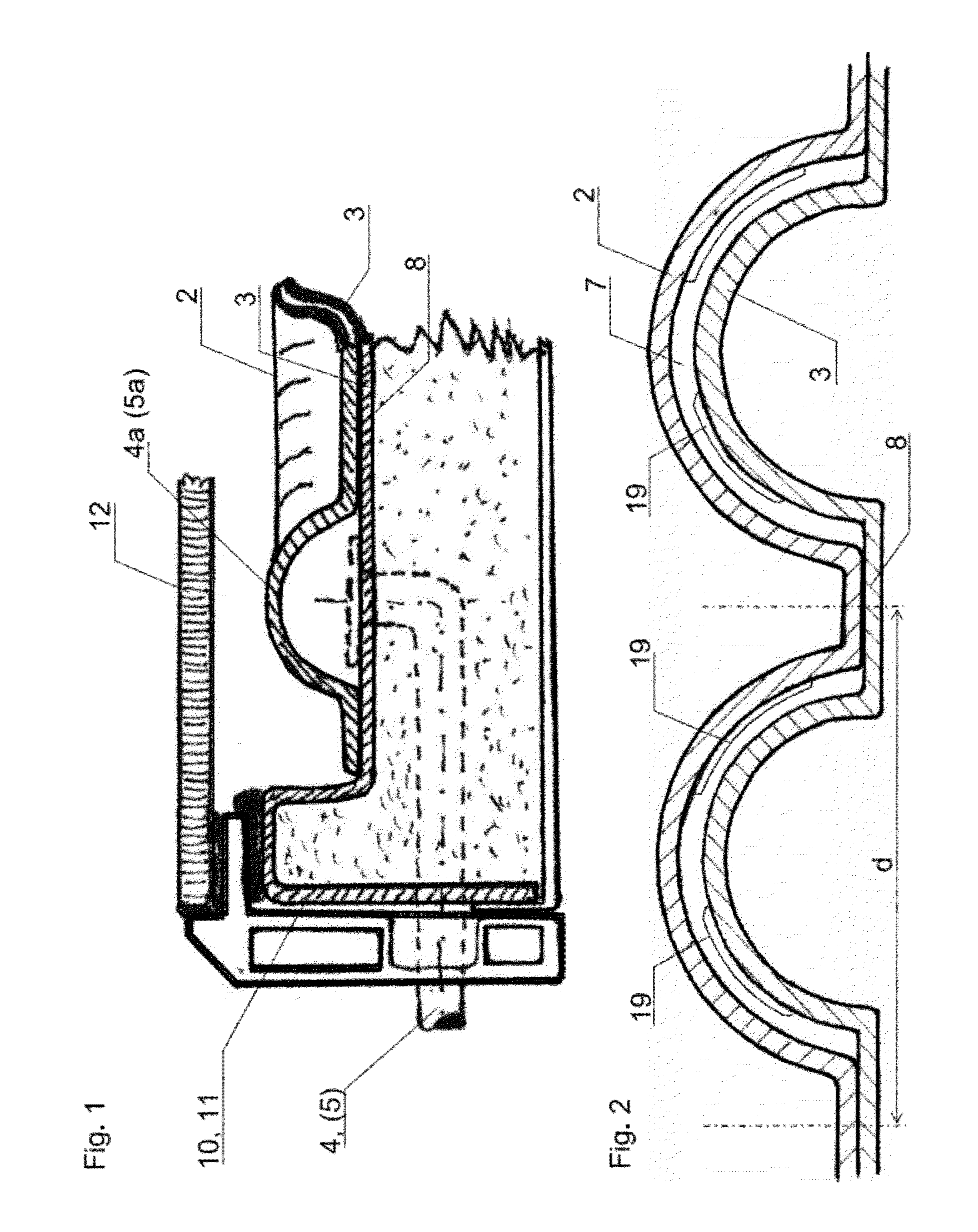
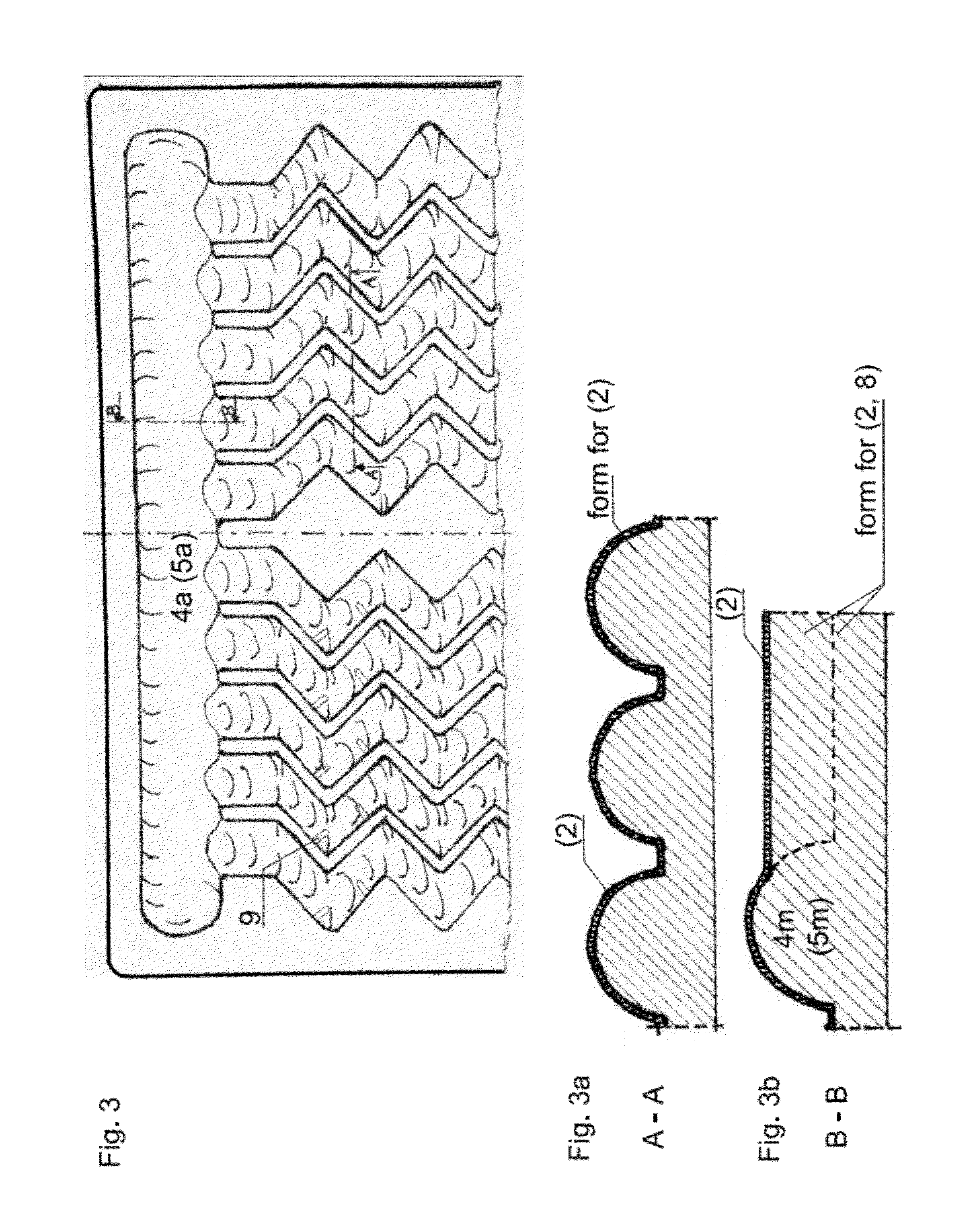
[0027]The invention is a heat exchanger of the plate type, please see FIG. 1, provided with an internal fluid passage for water or other liquid, comprising a first and a second plate (2, 3) whereof at least the first of the plates (2) is arranged to be exposed to a warmer or colder medium. The fluid may be water or another liquid such as antifreeze solution with a high heat capacity. An antifreeze solution will be advantageous in case of outdoor use in a climate with a risk of temperatures below zero degrees Celsius. The internal passage (6) between the two plates (2, 3) is constrained by manifolds (4a, 5a) to an inlet (4) and an outlet (5) for the fluid. The passage (6) forms a widening between the inlet (4) and outlet (5) in that it branches into several channels (7). The internal passage (6) is constrained between those two generally parallel plates (2, 3) and wherein the first and the second plate (2, 3) are formed in a structurally self-supporting polymer material.

[0028]In an a...


PUM


Abstract

A heat exchanger of a structurally self-supporting plate type and provided with an internal flow passage constrained between a first and a second plate and extending between an inlet and an outlet; The flow passage is subdivided in multiple generally parallelly directed longitudinally extending channels with the longitudinally extending channels having continuous joints formed by the two plates; The longitudinally extending channels have an arch-shaped cross-section and the arch-shape of the plates of the channels is in the same face direction orthogonal to the plates; The parallel running longitudinally extending channels include several laterally directed arches relative to their main axis in their longitudinal extension.

Description

[0001]The present invention is a heat exchanger of a structurally self-supporting plate type provided with an internal fluid passage between a first and a second plate (2, 3) whereof at least the first of the plates (2) is arranged to be exposed to a warmer or colder medium.BACKGROUND ART[0002]Swedish patent SE 533035 shows a heat exchange element of the plate type, with an internal fluid flow passage comprising two plates between an inlet and an outlet, and an interior passage that forms an extension between the inlet and outlet, where the passage is constrained between two parallel plates that are formed by a self-supporting polymer material. The two plates are joined with a number of point weldings distributed over the fluid passage area. A disadvantage of the Swedish patent is that the point welding process results in a quite flat surface. Such a flat surface reflects sunlight from the plate, particularly when the angle of the sun is inclined. An inclined sun angle also provides...

Claims


Application Information

Patent Timeline
Patent Type & Authority Applications(United States)
IPC IPC(8): F28F3/12
CPCF28F3/12F28D1/0308F28F3/046Y02E10/44F28F2270/00F24J2/205F24J2/245F24J2/248F24J2/201F24S10/501F24S10/504F24S10/742F24S10/748
Inventor HANSEN, PAL FRANCIS
Owner HIFORM
Why Eureka
Try Eureka