Radiation detection apparatus and radiation detection system

Active Publication Date: 2012-05-24
CANON KK
View PDF5 Cites 18 Cited by
  • Summary
  • Abstract
  • Description
  • Claims
  • Application Information

AI Technical Summary

Benefits of technology

[0005]In the radiation detection apparatus in which the scintillator is disposed on the side opposite to the radiation-incident side of the photodetector, the p

Problems solved by technology

One of the problems affecting this type of radiation detection apparatuses is that electromagnetic noise that originates from the X-r

Method used


Image

  • Radiation detection apparatus and radiation detection system
  • Radiation detection apparatus and radiation detection system
  • Radiation detection apparatus and radiation detection system

Examples


first embodiment

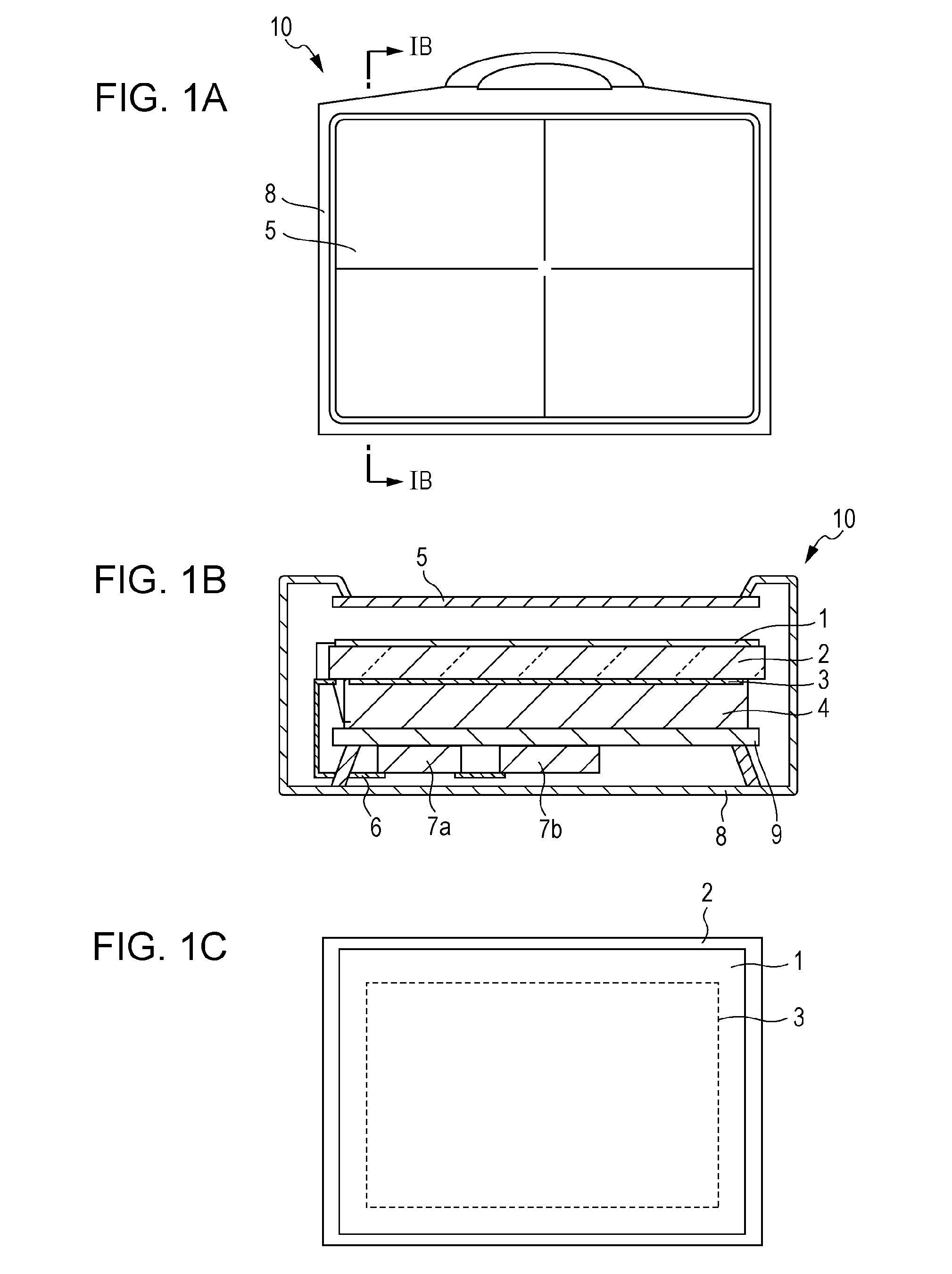
[0016]First, referring to FIG. 1A, FIG. 1B and FIG. 1C, a radiation detection apparatus 10 according to a first embodiment of the present invention is described below. FIG. 1A is a top view (front view), FIG. 1B is a cross-sectional view along sectional marks IB-IB of FIG. 1A, and FIG. 1C is a bottom view (back view) of the radiation detection apparatus 10.

[0017]As illustrated, the radiation detection apparatus 10 has a generally rectangular shape and is provided with a handle for maneuvering and positioning. A photoelectric conversion unit 3 is disposed on a side of a first surface of a substrate 2 such as a glass substrate with an insulating surface. The photoelectric conversion unit 3 includes a plurality of pixels arranged in a two-dimensional array. Each pixel includes a photoelectric conversion element and a switch element. Note that the substrate 2 and the photoelectric conversion unit 3 are placed such that radiation is incident on the substrate 2 from a second surface, oppo...

second embodiment

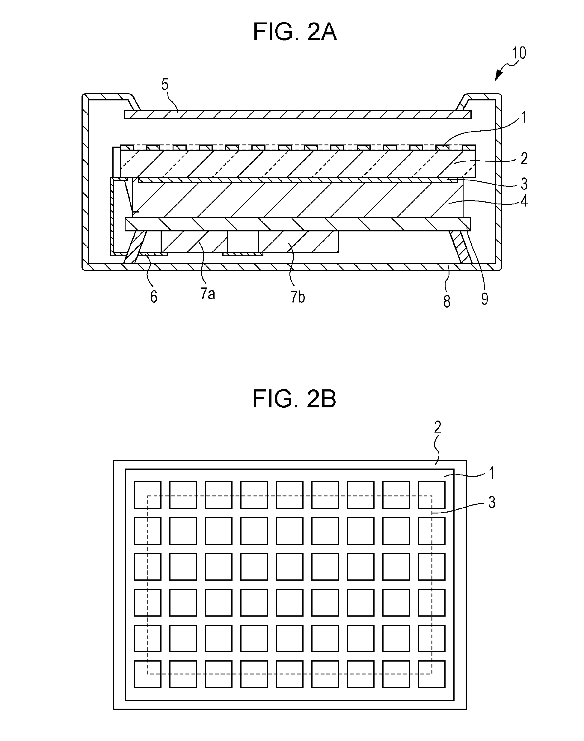
[0055]A second embodiment of the present invention is described below with reference to FIGS. 4A and 4B. The following description will focus on differences from the first embodiment described above, and similar structures or elements to those according to the first embodiment will be omitted.

[0056]A first difference is in that the substrate 2 has an insulating surface produced by performing a thinning process on the second surface of the substrate 2 at least in the area where the photoelectric conversion unit 3 is disposed. By employing the substrate 2 formed in the above-described manner, it is possible to reduce the attenuation of the radiation by the substrate 2 in the area corresponding to the photoelectric conversion unit 3. The thinning process of the substrate 2 may be performed at least for the area where the photoelectric conversion unit 3 is formed, although the whole second surface of the substrate 2 may be subjected to the thinning process.

[0057]In the thinning process,...

third embodiment

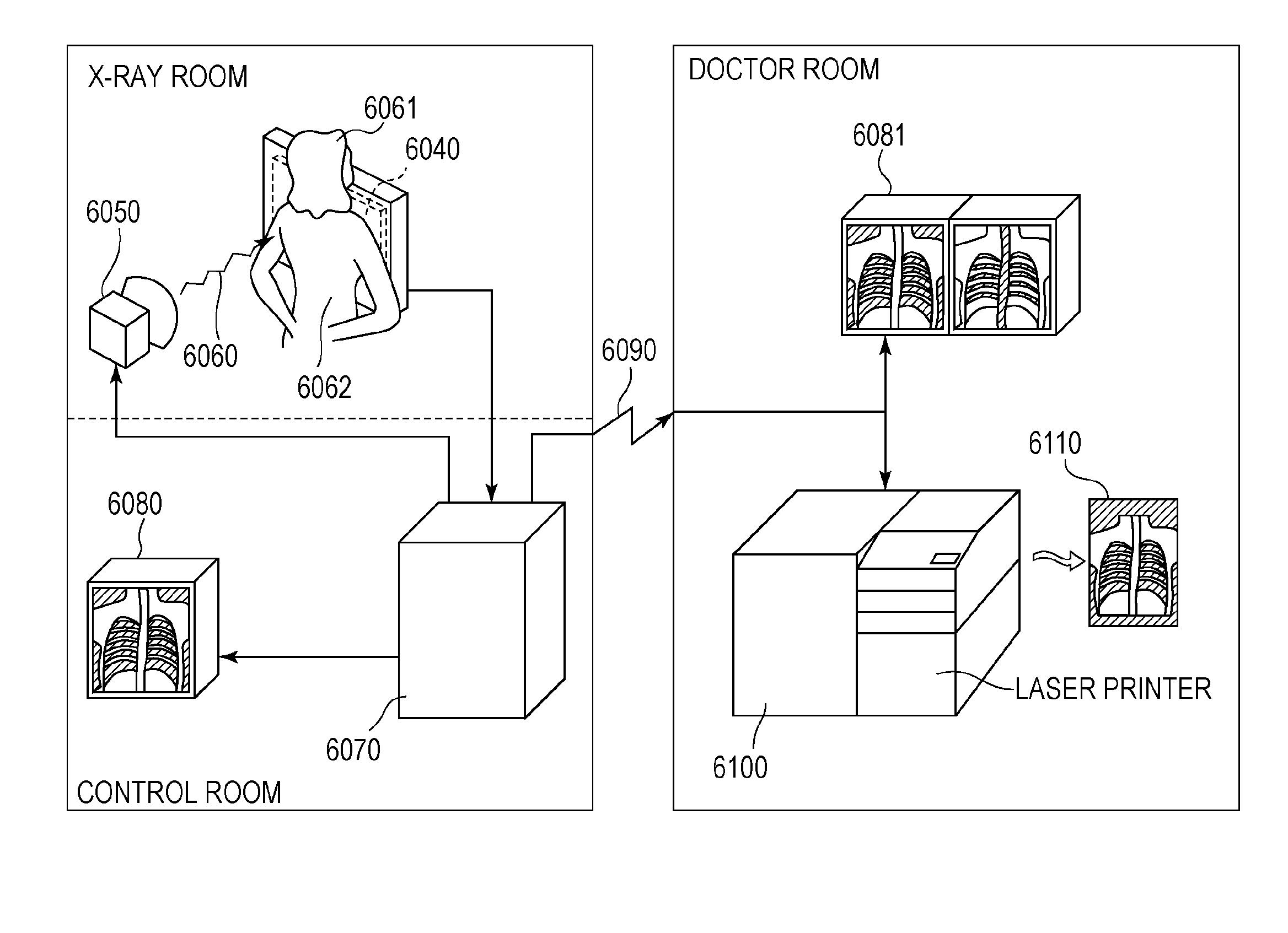
[0067]Referring to FIG. 6, a radiation detection system using a radiation detection apparatus according to an embodiment of the present invention is described below. An X-ray 6060 generated by an X-ray tube 6050 serving as a radiation source passes through a body part (chest) 6062 of a patient or a subject 6061 under examination and is incident on a radiation detection apparatus 6040 having a scintillator 4 disposed on a first surface of the photoelectric conversion unit 3. The incident X-ray includes information on the inside of the body of the patient 6061. In response to the incident X-ray, the scintillator 4 emits light. The emitted light is converted into electric charge by the photoelectric conversion unit 3. The electric charge is converted into a digital signal and is subjected to image processing by an image processor 6070 serving as a signal processing unit. A resultant image (obtained information) is displayed on a display 6080 serving as a display unit installed in a con...


PUM


Abstract

A radiation detection apparatus includes a scintillator configured to convert incident radiation into visible light, a photoelectric conversion unit and an electrically conductive member. The photoelectric conversion unit includes a two-dimensional array of pixels arranged on a substrate. Each pixel is configured to convert the visible light into an electric signal. The electrically conductive member is supplied with a fixed potential. The electrically conductive member, the substrate, the photoelectric conversion unit, and the scintillator are disposed in this order from the radiation-incident side of the radiation detection apparatus to the opposite side.

Description

BACKGROUND OF THE INVENTION[0001]1. Field of the Invention[0002]The present invention relates to a radiation detection apparatus and a radiation detection system applicable to a medical imaging apparatus, a non-destructive testing apparatus, an analysis apparatus using radiation, or the like.[0003]2. Description of the Related Art[0004]In recent years, thin-film semiconductor production technology has been used in the fabrication a detection apparatus or a radiation detection apparatus realized by a combination of a switch element such as a TFT (Thin-Film Transistor) and a conversion element such as a photoelectric conversion element. Japanese Patent Laid-Open No. 07-027864 discloses a radiation detection apparatus in which a solid-state photodetector is disposed on a side on which X-ray radiation emitted by an X-ray source is incident, and a scintillator is disposed on an opposite side. That is, the scintillator is disposed on the side opposite to the radiation-incident side of the...

Claims


Application Information

Patent Timeline
IPC IPC(8): G01T1/208G01T1/20
CPCG01T1/2928H01L27/14618H01L27/14676H01L27/14663H01L27/14632H01L2924/0002H01L2924/00
Inventor YOKOYAMA, KEIGOMOCHIZUKI, CHIORIWATANABE, MINORUKAWANABE, JUNFUJIYOSHI, KENTAROWAYAMA, HIROSHI
Owner CANON KK
Why Eureka
Try Eureka