
Distributed time-reversal mirror array

a mirror array and mirror array technology, applied in the field of distributed time reversal mirror arrays, can solve the problems of difficult synchronization of spatial coherence with sub nsec (0.2 nsec) among distributed sensors, and achieve the effects of efficient target tracking, easy and quick installation, and large array scalable

Inactive Publication Date: 2012-05-24
THE UNITED STATES OF AMERICA AS REPRESENTED BY THE SECRETARY OF THE NAVY
View PDF6 Cites 19 Cited by
  • Summary
  • Abstract
  • Description
  • Claims
  • Application Information

AI Technical Summary

Benefits of technology

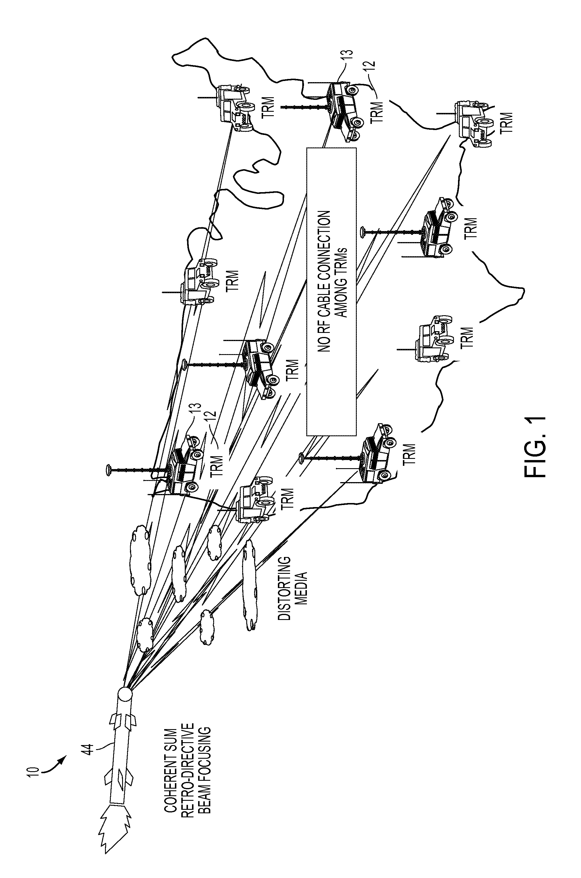
[0006]According to the invention, a distributed time reversal mirror array (DTRMA) system includes a plurality of independent, sparsely distributed time reversal mirrors (TRMs). Each of the TRMs includes an antenna; a transceiver connected to the antenna for transmitting a signal toward a target, for receiving a return, reflected signal from the target, and for retransmitting a time-reversed signal toward the target; means for phase-locking and for maintaining spatial and temporal coherences between the TRMs; and a computer including a machine-readable storage media having programmed instructions stored thereon for computing and generating the time-reversed retransmitted signal, thereby providing a phased array functionality for the DTRMA while minimizing distortion from external sources.
[0008]The invention has several advantages over the conventional phased array antennas, especially for high frequency OTHR cases. It provides time-reversal-based adaptive self-focusing of a beam on a target through distorting media to allow efficient target tracking. The invention also provides time-reversal-based multipath-enabled extended virtual aperture for high resolution beam focusing beyond the diffraction limit. It is cable-free, has easy and quick installation, and can be almost anywhere in a 2D or 3D arrangement. Also, it is scalable to a large array due to the easy installation of the modular, individual TRM. Furthermore, it has good SNR and SCR due to its good resolution.
[0009]Another significant advantage of the DTRMA is its capability of operating in an autonomous, unattended, and passive state, owing to the time-reversal's self-focusing feature. The beam may be sharply focused on the target due to the coherently synthesized extended aperture over the entire array.

Problems solved by technology

McGraw Hill Book (1990), is hampered by the required long RF cables which can raise various issues such as signal attenuation, phase instability due to thermal expansion, and difficulties in installation.
However, spatial coherence with sub nsec (<0.2 nsec) synchronization among distributed sensors has proven difficult.

Method used


Image

  • Distributed time-reversal mirror array
  • Distributed time-reversal mirror array
  • Distributed time-reversal mirror array

Examples


examples

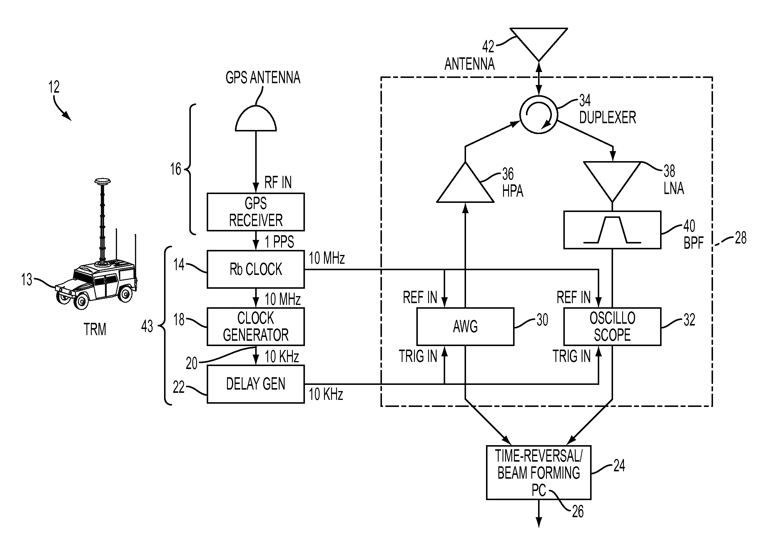
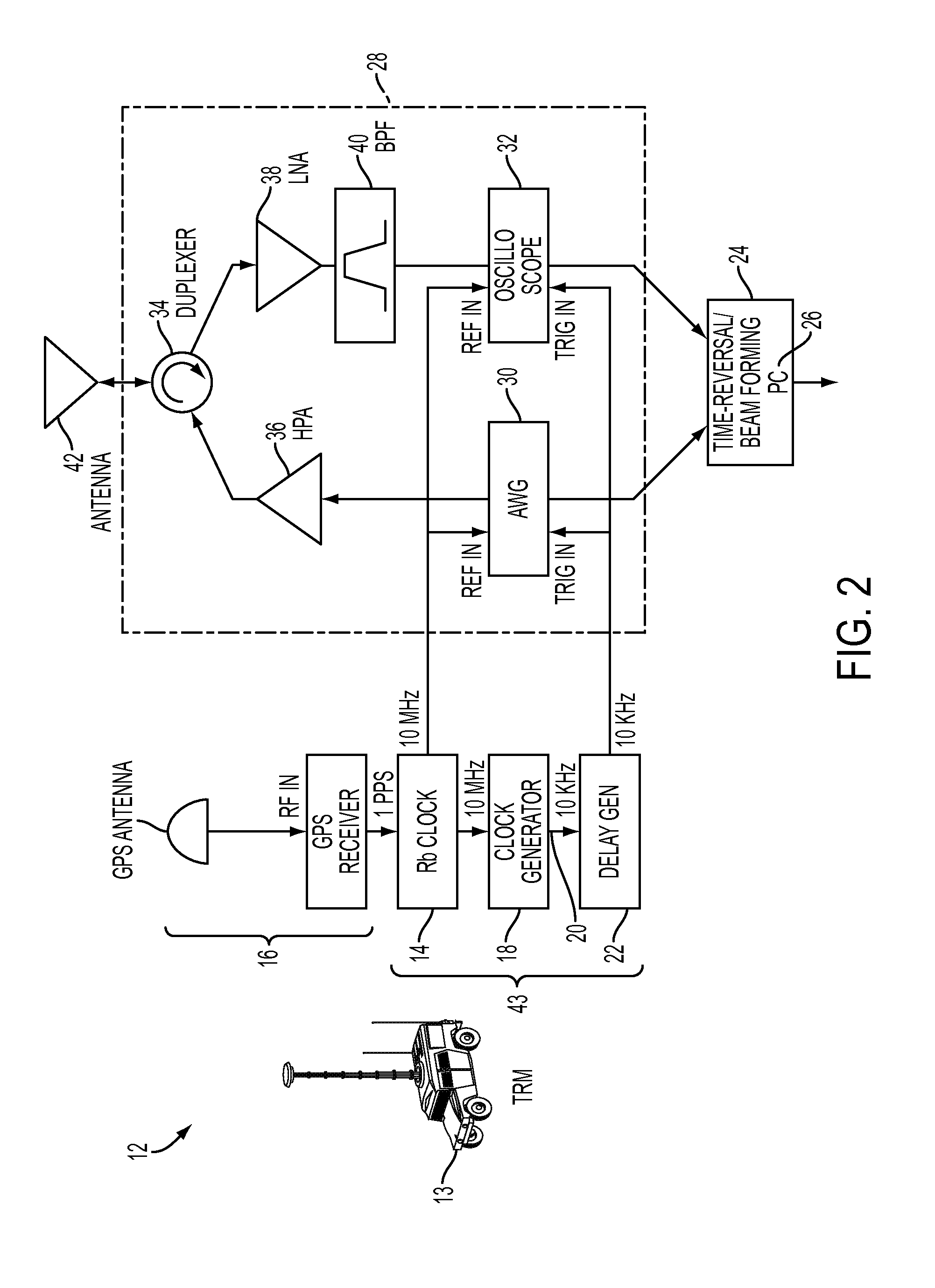
[0027]To demonstrate time reversal for a DTRMA 10, three time-reversal mirrors (TRMs) 12 were constructed as shown in FIG. 2 and set up on the roof of a four-story building. Each TRM 12 was connected with a respective HF vertical antenna 42 and a GPS unit 16. The components and instruments in each TRM 12 is tabulated in Table 1, below. All components were commercially available off-the-shelf products. These instruments were remotely controlled by MatLab or Labview codes through USB cables. Special care was taken to ensure that each TRM 12 was totally separate and independent without any RF cable connections among TRMs—a key feature of the DTRMA 10.

[0028]All the instruments (AWG, oscilloscope, precision synthesized clock generator and delay generator) in each TRM were phase-locked by the 10 MHz reference time base from their local GPS-disciplined Rubidium oscillator.

[0029]A 10 KHz TTL signal generated by the local frequency synthesizer was used to trigger all the instruments.

TABLE 1C...


PUM


Abstract

A distributed time reversal mirror array (DTRMA) system includes a plurality of independent, sparsely distributed time reversal mirrors (TRMs). Each of the TRMs includes an antenna; a transceiver connected to the antenna for transmitting a signal toward a target, for receiving a return, reflected signal from the target, and for retransmitting a time-reversed signal toward the target; means for phase-locking and for maintaining spatial and temporal coherences between the TRMs; and a computer including a machine-readable storage media having programmed instructions stored thereon for computing and generating the time-reversed retransmitted signal, thereby providing a phased array functionality for the DTRMA while minimizing distortion from external sources. The DTRMA is capable of operating in an autonomous, unattended, and passive state, owing to the time-reversal's self-focusing feature. The beam may be sharply focused on the target due to the coherently synthesized extended aperture over the entire array.

Description

CROSS-REFERENCE TO RELATED APPLICATIONS[0001]The present application is related to U.S. patent application Ser. No. 12 / 911,817, filed Oct. 26, 2010.FIELD OF THE INVENTION[0002]The invention is directed to a distributed time reversal mirror array (DTRMA) system employing a plurality of independent, sparsely distributed time reversal mirrors (TRMs), and more particularly to a DTRMA that is capable of operating in an autonomous, unattended, and passive state.BACKGROUND OF THE INVENTION[0003]Time-reversal has several powerful features that make it highly desirable for coherent radar imaging and tracking. These features include adaptive self-focusing of a beam on a target through distorting media, and high resolution imaging due to multipath-enabled extended virtual aperture. However, its implementation at high frequency over-the-horizon-radar (HF-OTHR), e.g. as described in J. F. Thomason, “Development of Over-the-Horizon Radar in the United States,” IEEE Radar 2003 Conference, Adelaide...

Claims


Application Information

Patent Timeline
Patent Type & Authority Applications(United States)
IPC IPC(8): G01S13/00
CPCG01S13/003G01S13/76G01S13/72G01S13/42
Inventor PAEK, EUNG GICHOE, JOON Y.
Owner THE UNITED STATES OF AMERICA AS REPRESENTED BY THE SECRETARY OF THE NAVY
Learn More