
Method on a network element for the purpose of synchronization of clocks in a network

a network element and network technology, applied in the direction of transmission, time-division multiplex, electrical equipment, etc., can solve the problems of affecting the synchronization of clocks in the network, the degradation of accuracy is related to a higher number of control loops, and the forwarding of time packets from one port to another port, so as to achieve the same level of degradation, reduce or remove the load of time synchronization, and increase the time synchronization performance of the network elemen

Inactive Publication Date: 2012-05-24
ONTIME NETWORKS
View PDF20 Cites 26 Cited by
  • Summary
  • Abstract
  • Description
  • Claims
  • Application Information

AI Technical Summary

Benefits of technology

[0123]The present invention provides a solution where the accuracy of Transparent Clocks (only one control loop between the grand master and a slave) and the principles of having separate time synchronization properties similar to Boundary Clocks of each port of the network element can be combined.
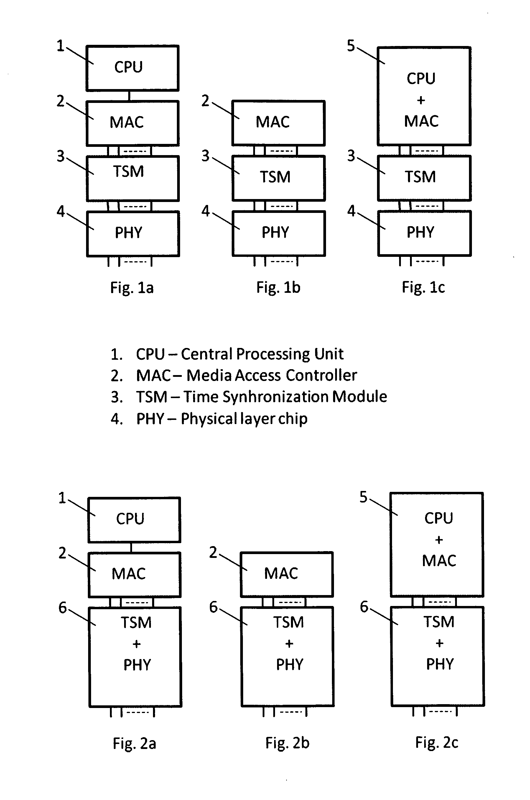
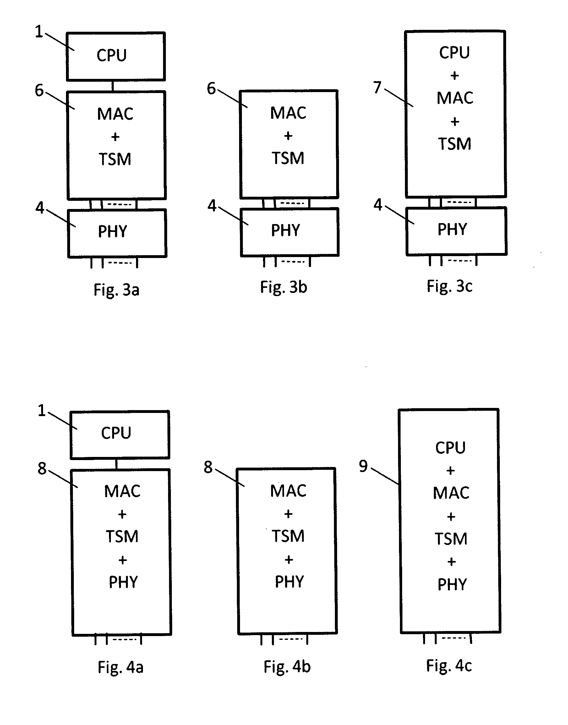
[0127]Most implementations of time synchronization on network elements available today are based on pairing the time stamps and time synchronization packets in the CPU. The CPU performs all calculations based on the time stamps that are required for local clock control and for insertion of time stamps in the time synchronization packets sent by the network element. The present invention describes a method where the CPU need not take part in the insertion or updates of time stamps or residence times of time synchronization packets. An implementation of time synchronization in the CPU can then be made simple or may not be required at all. Reducing the need for a CPU to perform time synchronization has the benefit of handling higher time synchronization network load. Being able to handle a high time synchronization load is particularly important on network elements such as switches and routers as well as on time servers, where the time synchronization load can be vast.
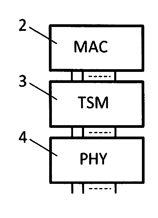
[0129]The present invention may be used for synchronization of end node clocks via a network, where the network elements perform time stamping of incoming and outgoing time packets in a time synchronization module close to the physical layer and where these time stamps are kept in a data base of the time synchronization module. The time synchronization module reduces or removes the time synchronization load on the CPU of the network element and therefore increases the time synchronization performance of the network element. The invention provides accuracy (same level of degradation) as a Transparent Clock and the same property as a Boundary Clock with respect to achieving good security properties on the network element since time sync packets are not sent from one port to another.

Problems solved by technology

This degradation of accuracy relates to a higher number of control loops for networks with Boundary Clocks compared to networks with Transparent Clocks.
Forwarding of time packets from one port to another port can be a problem in case the Transparent Clock is a router or in case packet encryption is used.

Method used


Image

  • Method on a network element for the purpose of synchronization of clocks in a network
  • Method on a network element for the purpose of synchronization of clocks in a network
  • Method on a network element for the purpose of synchronization of clocks in a network

Examples


Embodiment Construction

Definitions

[0145]Update, shall be interpreted as modifying a time stamp or residence time by adding or subtracting to the said time stamp or residence time, when used in relation to time stamps or residence time.

[0146]Time information, can be ingress time stamps, egress time stamps, residence time, a time interval or system time depending on the definition in the subtext where it is used.

[0147]Recidence time, shall be interpreted as the time which a time synchronization packet resides in a switch, router, computer or other embedded network device. The residence time may also contain other time measures such as asymmetric delay or cable delays components.

[0148]Send packet, from the ICnt to the MAC or from the ECnt to the EPT shall in case the packet is modified be interpreted as containing a new MAC checksum. Other packet header parameters may also be modified if required. E.g. the UDP checksum must also be re-calculated or set to zero if this field originally was different from zero...


PUM


Abstract

It is described a method on a network element with one or more communication ports for transmitting and receiving data packets to and from other network elements in a network for the purpose of synchronization of clocks in a network, said network element comprising a time synchronization module, a time synchronization module clock and a database.

Description

TECHNICAL FIELD[0001]The present invention relates to a method on a network element with one or more communication ports for transmitting and receiving data packets to and from other network elements in a network for the purpose of synchronization of clocks in a network.BACKGROUND[0002]Time synchronization in a network based on IEEE1588 or NTP / SNTP is based on time stamping of incoming and outgoing time packets on the time server (time source) and the time clients. Accurate time synchronization can be achieved if the time stamping is performed close to the physical layer of the network element. Measurement of—and correction for packet delay of the time packets through network elements such as switches and routers on the network paths between the time server and the clients have also impact on time synchronization accuracy. IEEE1588, Std 2002 and Std 2008, defines time servers as Master Clocks (MC), network elements such as switches and routers with support for measurement of—and cor...

Claims


Application Information

Patent Timeline
Patent Type & Authority Applications(United States)
IPC IPC(8): H04J3/06
CPCH04J3/0667H04J3/0673H04L69/28H04L63/0428H04L63/105H04J3/0697
Inventor HOLMEIDE, OYVINDKYLLESO, PAL-JORGEN
Owner ONTIME NETWORKS
Learn More