
Intermediate transfer belt

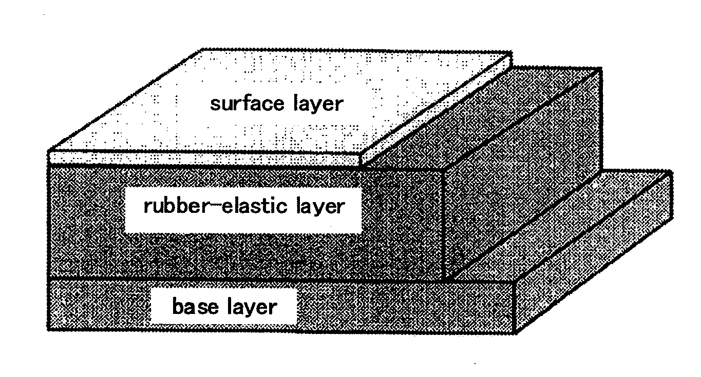
a transfer belt and intermediate technology, applied in the field of intermediate transfer belts, can solve the problems of reducing image quality, cracking or peeling of the surface layer, and it is extremely difficult for an intermediate transfer belt having a thin surface layer to achieve high external friction resistance, and achieves excellent durability, increased rubber hardness of the rubber-elastic layer, and the effect of preventing the concentration of stress on the surface layer

Inactive Publication Date: 2012-05-24
GUNZE LTD
View PDF1 Cites 8 Cited by
  • Summary
  • Abstract
  • Description
  • Claims
  • Application Information

AI Technical Summary

Benefits of technology

[0028]In the intermediate transfer belt for an image-forming device of the present invention, by increasing the rubber hardness of the rubber-elastic layer only in the portion that is in contact with the surface layer, the concentration of stress on the surface layer can be prevented, and excellent durability can be attained while maintaining high image quality.
[0029]Thus, because of the excellent durability and high image quality, the intermediate transfer belt for an image-forming device of the present invention can be suitably used as an intermediate transfer belt for image-forming devices employing an electrophotographic system such as copying machines (including color copying machines), printers, facsimiles, etc.

Problems solved by technology

However, since the intermediate transfer belt for an image-forming device receives external force from paper and a sliding member such as cleaning blade, roller, that is in contact with a belt surface when the surface layer has a thin film, stress applied to the belt is concentrated on the thin film surface layer, which causes problems such as cracking or peeling of the surface layer.
Moreover, even when the hardness of the entire belt is increased to overcome such a problem, although excellent durability can be attained, there is a problem of reducing the image quality.
Thus, it is extremely difficult for an intermediate transfer belt having a thin surface layer to attain high external friction resistance, etc., while maintaining high image quality.

Method used


Image

  • Intermediate transfer belt
  • Intermediate transfer belt
  • Intermediate transfer belt

Examples


example 1

(1) Formation of the Base Layer

[0200]Under a nitrogen flow, 47.6 g of 4,4′-diaminodiphenylether (ODA) was added to 488 g of N-methyl-2-pyrrolidone. The mixture was maintained at 50° C. while stirring to achieve complete dissolution. To this solution was added 70 g of 3,3′,4,4′-biphenyl tetracarboxylic dianhydride (BPDA) to yield 605.6 g of a polyamic acid solution. The obtained polyamic acid solution had a number average molecular weight of 19,000, a viscosity of 40 poise, and a solids content of 18.1 wt. %.

[0201]Subsequently, 21 g of acidic carbon black (pH 3.0) and 80 g of N-methyl-2-pyrrolidone were added to 450 g of the polyamic acid solution. Carbon black (CB) was uniformly dispersed using a ball mill. This master batch solution had a solids content of 18.6 wt. %, and a CB concentration of 20.5 wt. % in the solids content.

[0202]Then, 273 g of the solution was collected and poured into a drum. The solution was molded under the following conditions:

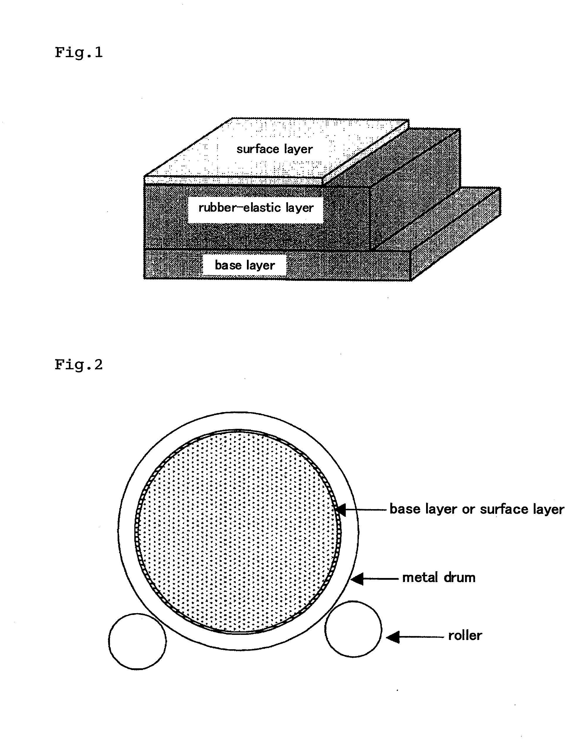
[0203]Rotary drum: A metal drum...

example 2

[0223]A multilayered belt was produced in the same manner as in Example 1 except that the amount of aluminum borate incorporated in the rubber layer was 5 wt. % and the volume fraction thereof was 1.96%.

[0224]The obtained multilayered belt had a thickness of 334 μm, an outer circumferential length of 945.0 mm, a static friction coefficient of 0.29, a surface resistivity of 2×10¹¹ to 4×10¹¹Ω / , a volume resistivity of 6×10¹⁰ to 9×10¹⁰Ω·cm, and a surface roughness (Rz) of 0.7 μm.

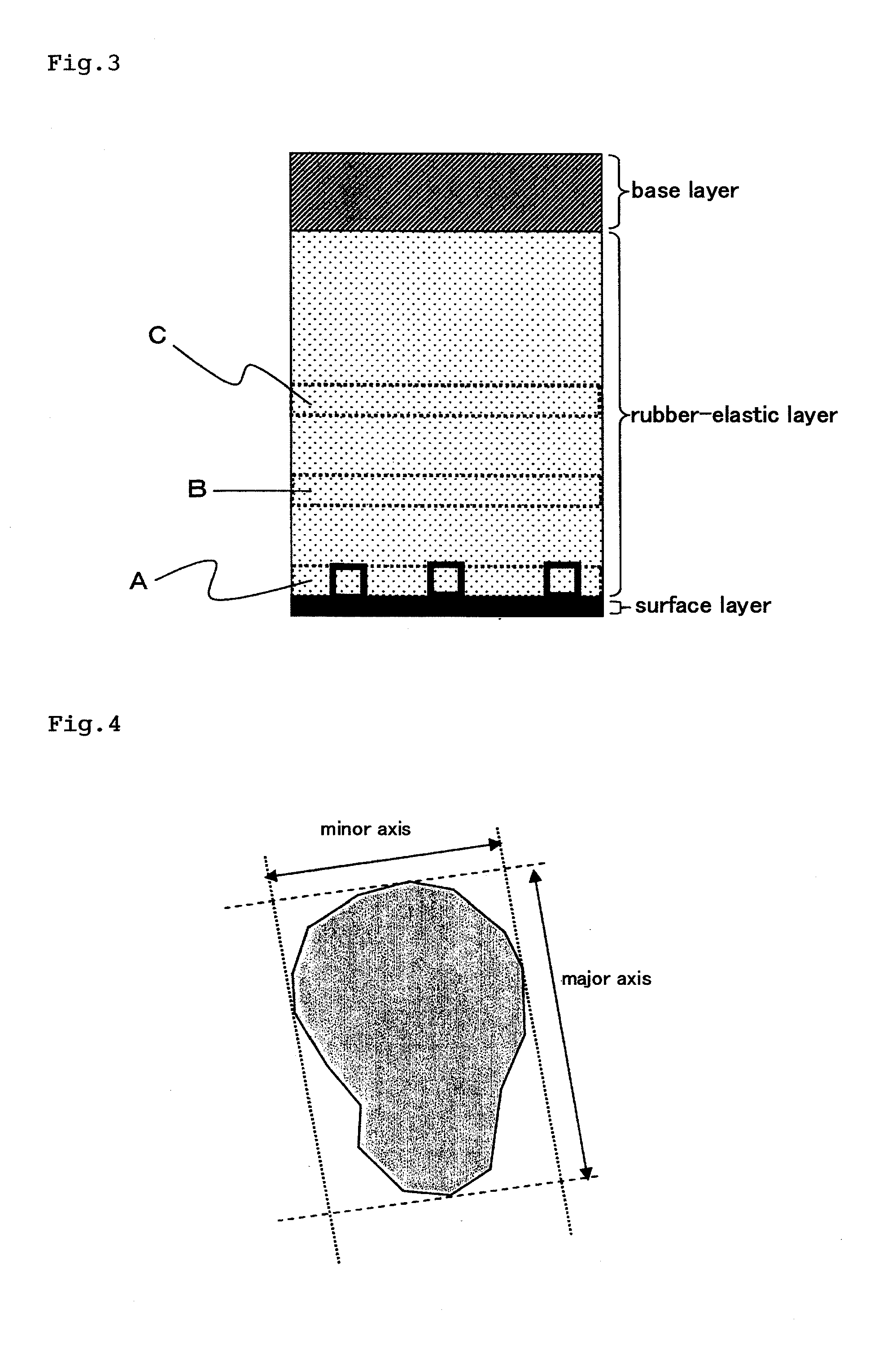
[0225]Further, the cross section of the multilayered belt was observed by a scanning electron microscope (SEM), and the mass concentration ratios of aluminum (M1 / M2 and M1 / M3) were determined by EDX. The results showed that M1 / M2=12.5 and M1 / M3=24.8. These results confirmed that the concentration of the filler in the region from the interface between the surface layer and the rubber-elastic layer toward the base layer to a depth of 20 μm was higher than that in the central portion of the rubber layer.

example 3

[0226]A multilayered belt was produced in the same manner as in Example 1 except that the aluminum borate incorporated in the rubber layer was in the form of particles (Alborite, produced by Shikoku Chemicals Corporation, average particle diameter D50=2.6 μm), the amount of aluminum borate was 5 wt. %, and the volume fraction thereof was 1.96%.

[0227]The obtained multilayered belt had a thickness of 337 μm, an outer circumferential length of 945.0 mm, a static friction coefficient of 0.29, a surface resistivity of 2×10¹¹ to 4×10¹¹Ω / , a volume resistivity of 8×10¹⁰ to 1×10¹¹Ω·cm, and a surface roughness (Rz) of 0.7 μm.

[0228]Further, the cross section of the multilayered belt was observed by a scanning electron microscope (SEM), and the mass concentration ratios of aluminum (M1 / M2 and M1 / M3) were determined by EDX. The results showed that M1 / M2=11.5 and M1 / M3=13.7. These results confirmed that the concentration of the filler in the region from the interface between the surface layer an...


PUM

PropertyMeasurementUnit
Lengthaaaaaaaaaa
Lengthaaaaaaaaaa
Lengthaaaaaaaaaa

Abstract

A main object of the present invention is to provide an intermediate transfer belt for image-forming devices and a method for producing the intermediate transfer belt, the intermediate transfer belt having excellent image transfer to rough paper and resistance to abrasion and being free from problems such as filming, by forming a surface layer that has excellent resistance to abrasion and in which defects such as pinholes are not likely to occur even when the surface layer is thinned.An intermediate transfer belt for image-forming devices and a method for producing the same, the intermediate transfer belt comprising at least the following three layers laminated in the described order: (a) a base layer formed from resin, (b) a rubber-elastic layer formed from a rubber or elastomer, having a thickness of 200 to 400 μm and (c) a surface layer formed from resin, having a thickness of 0.5 to 6 μm, wherein the intermediate transfer belt has the following properties: (i) the dynamic ultramicro hardness (ISO14577-1) measured from the surface layer side is 2.5 to 4.5 N / mm2 at the indentation depth of 2 μm, and 1.0 N / mm2 or less at the indentation depth of 10 μm, and / or (ii) the rubber-elastic layer contains a filler in a proportion of 0.4 to 4.0 vol. %, and the ratio (M1 / M3) of the mass concentration M1 of the filler in the region from the interface between the surface layer and the rubber-elastic layer toward the base layer to a depth of 20 μm, to the mass concentration M3 of the filler in the region from 120 μm to 140 μm in depth from the interface between the surface layer and the rubber-elastic layer toward the base layer is 1.3 or higher.

Description

TECHNICAL FIELD [0001]The present invention relates to an intermediate transfer belt for image-forming devices such as copying machines, printers, and facsimiles.BACKGROUND ART [0002]To improve the quality of images obtained by image-forming devices, two-layer or three-layer intermediate transfer belts including a rubber-elastic layer formed of a rubber-elastic resin, etc., have been suggested (for example, see Patent Literature 1).[0003]Since such an intermediate transfer belt having a rubber-elastic layer has excellent flexibility, a stable transfer image area can be formed on the intermediate transfer belt by the uniform contact between the belt and a photo conductor, etc., and stress applied to toner between the belt and the photo conductor, etc., can be reduced. Therefore, by using an intermediate transfer belt including a rubber-elastic layer, missing defects on line image can be prevented, and fine line printing definition can be improved. Further, it is also known that when ...

Claims


Application Information

Patent Timeline
IPC IPC(8): B32B25/08B32B38/18B32B7/022
CPCB32B5/145Y10T428/24967B32B7/12B32B27/08B32B27/20B32B27/281B32B27/304B32B27/40B32B2250/03B32B2250/04B32B2250/24B32B2264/102B32B2264/104B32B2264/108B32B2274/00B32B2305/30B32B2307/536B32B2307/54B32B2307/554B32B2413/00B32B2559/00G03G15/1685G03G15/162B32B7/02B32B7/022G03G15/16B32B25/02B32B25/08
Inventor KURAOKA, TAKASHIMITSUI, SATOSHIMATSUMURA, YUUKI
Owner GUNZE LTD
Learn More