[0020]According to the marine propulsion device as described in claim 1, the so-called
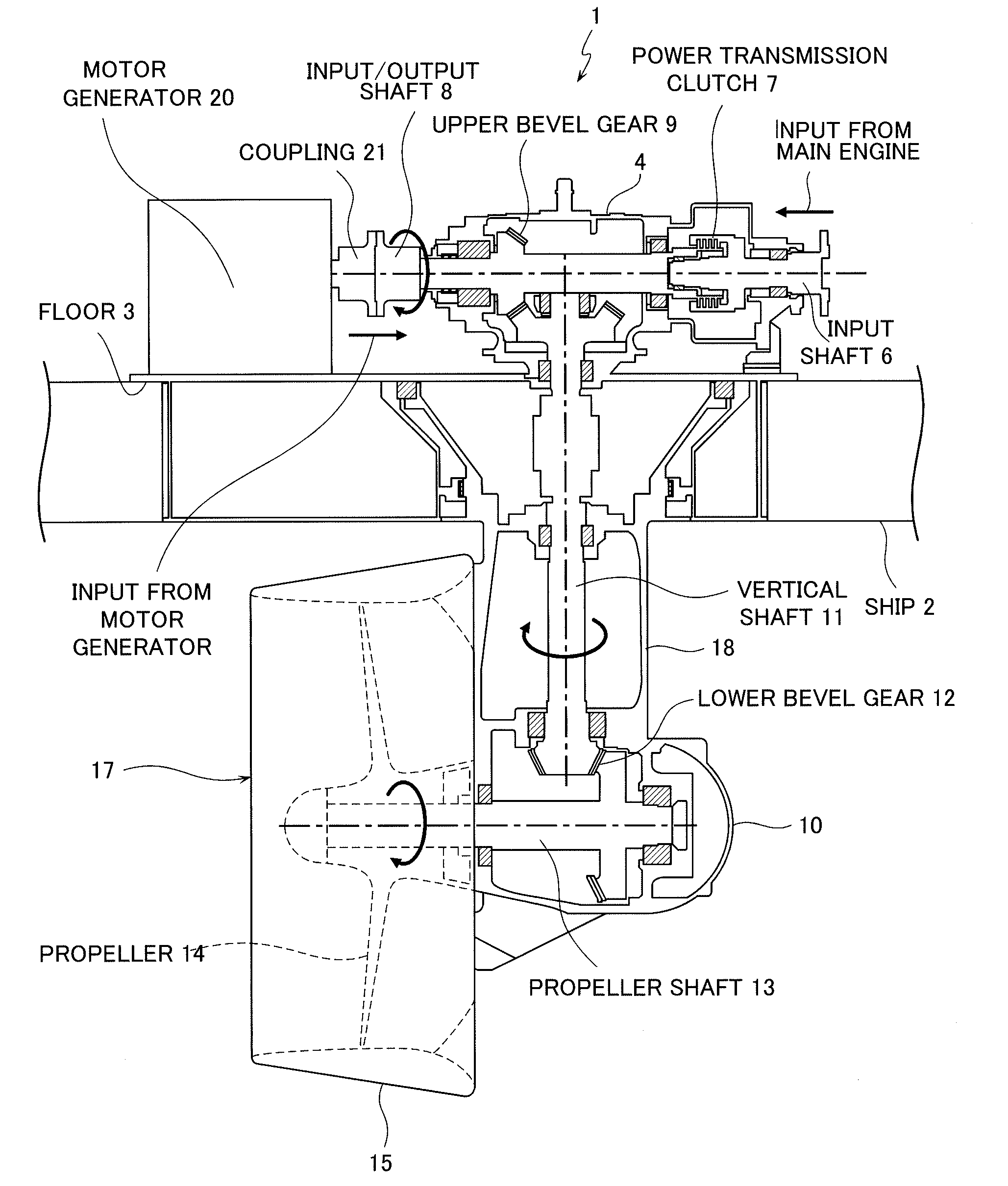
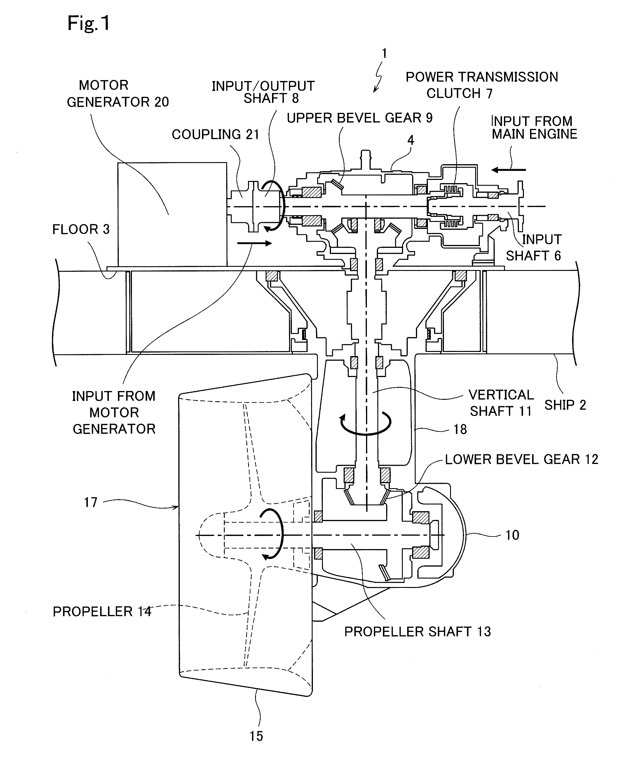
azimuth thruster adapted to set the propulsion direction by revolving the horizontal propeller shaft around the vertical shaft for transmitting the power adopts the structure in which the main engine is connected only to one end side of the input / output shaft of the
azimuth thruster through the single
power transmission clutch without interposing a complicated speed reducing mechanism, and the motor generator is direct-coupled to the other end side. Therefore, a simple and compact-sized configuration can be realized and assembling to the ship can be facilitated to reduce the manufacturing cost. Furthermore, even when one of the main engine and the motor generator is broken, the operation can be performed without a hindrance, and the clutch is only one
power transmission clutch, being simple without a speed
reducer, so that the reliability as the marine propulsion device is high. Furthermore, since adopted is a
hybrid system in which a power source as the propulsion device is combination of the main engine and the motor generator, the efficient drive control fit for the load state of the ship can be realized to reduce fuel consumption, lower the output of the main engine and enable downsizing. With this
advantage, the running cost and the
greenhouse gas emission amount can be reduced, and in addition, the degree of freedom in
layout can be heightened by downsizing.
[0021]According to the marine propulsion device as described in claim 2, the motor generator is fixed directly to the base part, which is mounted at the bottom of the ship and to which the horizontal input / output shaft is fitted, and the motor generator is direct-coupled to the other end side of the input / output shaft, so that the configuration as the whole device is further compact-sized. Furthermore, in performing the operation for installing the marine propulsion device in the ship in a shipyard, it will suffice to
mount the base part at the bottom of the ship and connect the main engine of the ship to the driving force transmission clutch, so the operation is simple. That is, apart from the operation for mounting the base part at the bottom of the ship, it is not necessary to
mount the motor generator at a required position of the bottom of the ship or again connect the same to the input / output shaft on the base part, and therefore the man-hour can be decreased to realize further reduction in manufacturing cost.
[0022]According to the marine propulsion device as described in claim 3, in the motor propulsion, the slip control conducted in the low-speed drive state of the main engine is not needed, so that generation of heat and
power loss in the
power transmission clutch caused by the slip control can be reduced. Further, in the case of stopping the main engine in the motor propulsion, the running cost and the
greenhouse gas emission amount during that engine stop can be decreased. The motor generator sharing the load with the main engine may drive just for its share of the output, so the motor generator can be miniaturized to be carried integral on the base part of the azimuth thruster without a hindrance. The operation in the
low load region of the main engine is decreased, and the operation in the efficient load region is possible so that fuel consumption is improved. In the motor propulsion, since the motor generator is driven as the motor, the torque can be 100% output even in the low rotation state to quickly respond to the propeller load and facilitate fine adjustment. Thus, ship handling performance can be improved. In the
hybrid propulsion, while the propeller drive having good transmission efficiency is performed by the main engine, the motor generator can be used as the motor or the generator according to the load state, so that in acceleration, torque assist can be obtained from the motor generator acting as a motor. In cruising and deceleration, the motor generator acting as a generator performs power generation to thereby charge the condensed
discharge mechanism such as a battery provided at need, and surplus energy can be recovered.
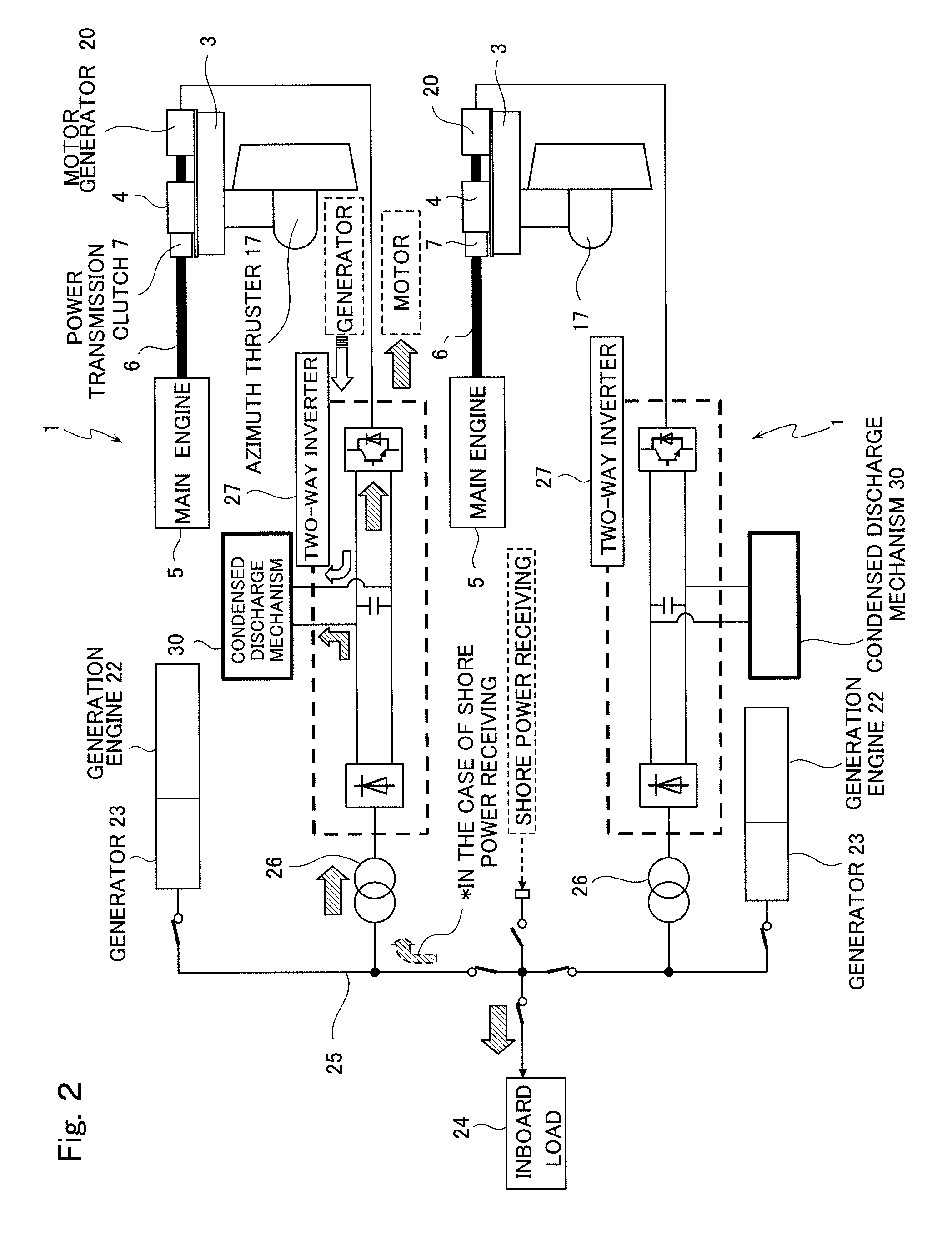
[0023]According to the marine propulsion device as described in claim 4, the main engine and the two-way
inverter are integrated-controlled by the controller to thereby smoothly switch between the motor generator and the main engine. In the motor propulsion, the motor generator is speed-controlled to thereby enable fine ship handling in the
low speed region, and in the
hybrid propulsion, while the output of the main engine is taken as base load, the controller controls the motor generator as a motor according to the ship running state, thereby assisting the main engine, or the motor generator is acted as the generator to generate power with surplus energy. Thus, efficient ship running is enabled according to the load state. In addition, since the main engine can be operated in the efficient region, fuel consumption can be reduced.
[0024]According to the marine propulsion device as described in claim 5, the power to the motor can be supplied from the generation engine and the condensed
discharge mechanism, so that the capacity of the generation engine can be made smaller than the capacity of the motor generator, and compactness can be realized by downsizing. Further, the power supply is given redundancy so that even when one is broken, the operation can be performed without a hindrance.
[0025]According to the marine propulsion device as described in claim 6, the controller always monitors the charging depth of the condensed
discharge mechanism, and when it reaches a certain charging depth or more, generation from the motor generator is paused to avoid
overcharge.

