High voltage electro inductive swivel

a high-voltage, inductive technology, applied in the direction of inductances, waterborne vessels, electrical devices, etc., can solve the problems of high voltage, large, expensive, and relatively inefficient converter stations, and achieve the effect of not involving the risk of the swivel overheating

Inactive Publication Date: 2012-05-31
SINGLE BUOY MOORINGS INC
View PDF8 Cites 23 Cited by
  • Summary
  • Abstract
  • Description
  • Claims
  • Application Information

AI Technical Summary

Benefits of technology

[0026]The radial arms of the power swivel according to invention may define an open area between adjacent radial arms for forming an axial passage for a cooling medium. In this manner cooling fluid, for instance a

Problems solved by technology

Normally, such barges are spread-moored in a manner which does not allow the barge to weathervane around the mooring in response to the action of wind, waves and currents.
Furthermore, offshore transmission of large amounts of AC electric power over long distances requires very high voltages in order to avoid the need for large cross-section copper cables and by consequence very heavy and expensive cables.
A solution to reduce the cross section of the conductor in submarine cables is to transform the electric AC power into DC power, but this requires

Method used


Image

  • High voltage electro inductive swivel
  • High voltage electro inductive swivel
  • High voltage electro inductive swivel

Examples


Embodiment Construction

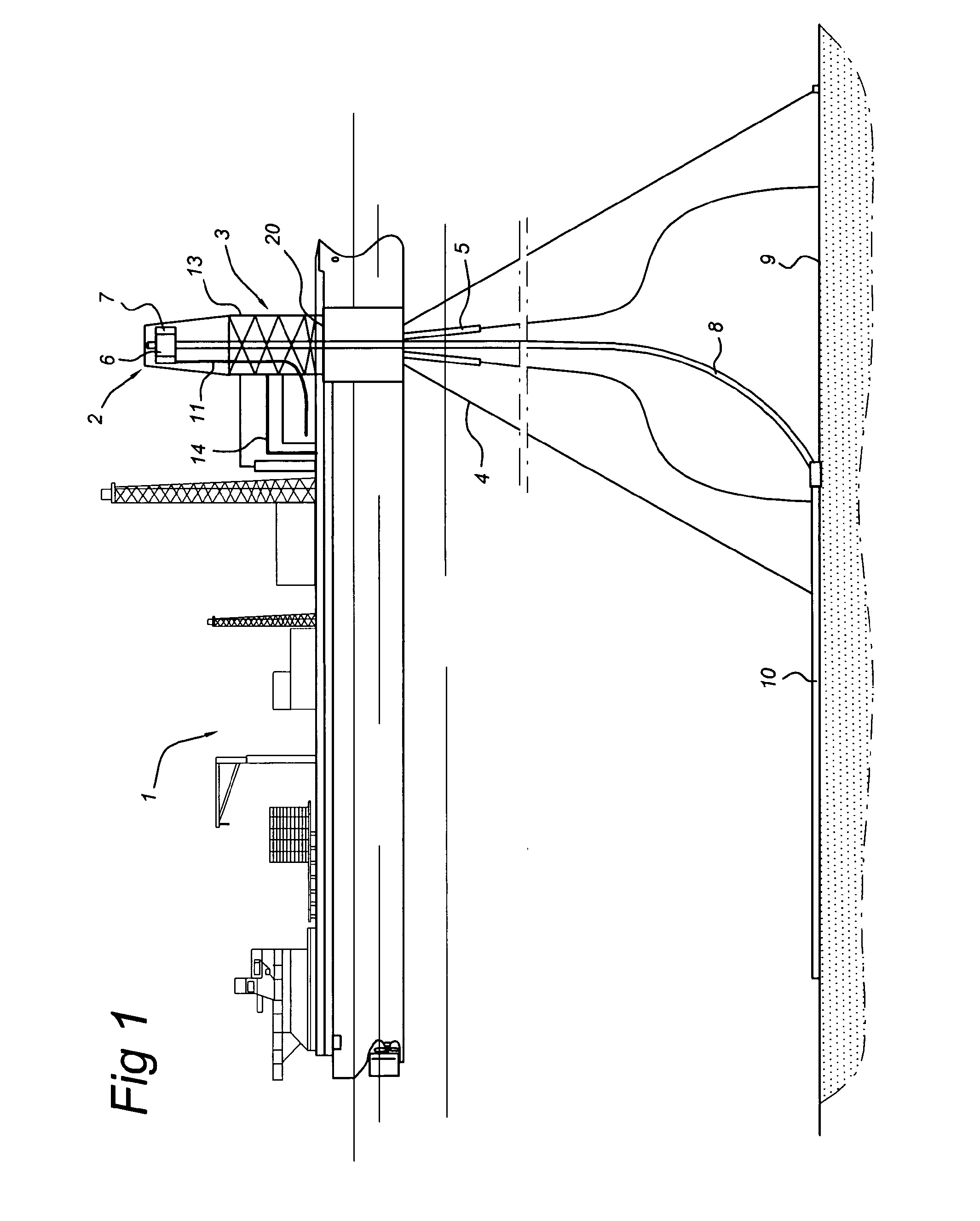
[0037]In the following description the floating unit 1 is formed by a FPSO, but the power swivel according to the invention is not limited to use on an FPSO but could be applied on any type of vessel, floating power unit and even floating wind turbines, floating wave energy converters etc.

[0038]FIG. 1 shows a single point floating unit 1 rotatably coupled to a turret 3 which is anchored to the sea bed 9 via mooring lines 4 so that the floating unit 1 can weathervane about the turret 3. The floating unit 1 has a vertically extending aperture 20 through its hull in which the turret 3 is mounted in a rotatable manner, supported by upper and lower bearings (not shown).

[0039]A plurality of mooring lines 4, such as anchor chains, only a part of which is shown for convenience, are attached to the turret 3 in a known manner, for example via a chain stopper to a chain hawse pipe. In this way, the floating unit 1 is able to rotate around the turret 3 and the anchor chains in response to wave,...


PUM


Abstract

Power swivel for transmitting electrical power from a first terminal to a second terminal, includes a central part with a hub and an outer ring of a magnetic material, coaxial with and surrounding the hub, the outer ring and central part being rotatable relative to one another around a vertical axis, at least two radial arms of a magnetic material projecting from the hub or from the outer ring, adjacent arms being spaced-apart, each arm carrying a conductor wound around the arm to form a coil for generating a magnetic flux along a radial flux path through the arm, the conductors being connected to the first terminal, wherein the outer ring or the hub has a cylindrical surface at close proximity to free ends of the arms, a plurality of axially extending conductors being distributed along the circumference of the outer ring or hub at or near the cylindrical surface.

Description

FIELD OF THE INVENTION[0001]The present invention relates to a high voltage electro inductive power swivel. The invention in particular relates to a power swivel for use in a weathervaning offshore structure, such as a floating single point moored unit.BACKGROUND OF THE INVENTION[0002]It is known to generate electrical power on-board floating barges located offshore and to transfer the power to shore and into the electricity network. Normally, such barges are spread-moored in a manner which does not allow the barge to weathervane around the mooring in response to the action of wind, waves and currents. Alternatively, such barges may be turret-moored wherein mooring lines are attached to a turret rotatably mounted in the hull of the barge. This system allows the vessel to weathervane around the turret and the mooring lines in response to wind, wave and current action.[0003]If a barge is turret-moored in this way, an electrical swivel apparatus is required on top of the turret in orde...

Claims


Application Information

Patent Timeline
IPC IPC(8): H01F30/06
CPCH01F38/18B63B21/507
Inventor BEDINI, MAURO
Owner SINGLE BUOY MOORINGS INC
Why Eureka
Try Eureka