
Unattended Ground Sensors

Inactive Publication Date: 2012-05-31
THE BOEING CO
View PDF4 Cites 17 Cited by
  • Summary
  • Abstract
  • Description
  • Claims
  • Application Information

AI Technical Summary

Benefits of technology

[0015]In contrast to prior art systems, an illustrative embodiment provides a small, simple and inexpensive ground sensor that may be used in a network of such sensors. The simplified design of the sensors allows rapid deployment, collection and subsequent redeployment. The lesser expense of the sensors means that loss of individual sensors, either through damage or by inadvertently being left behind, is tolerable.
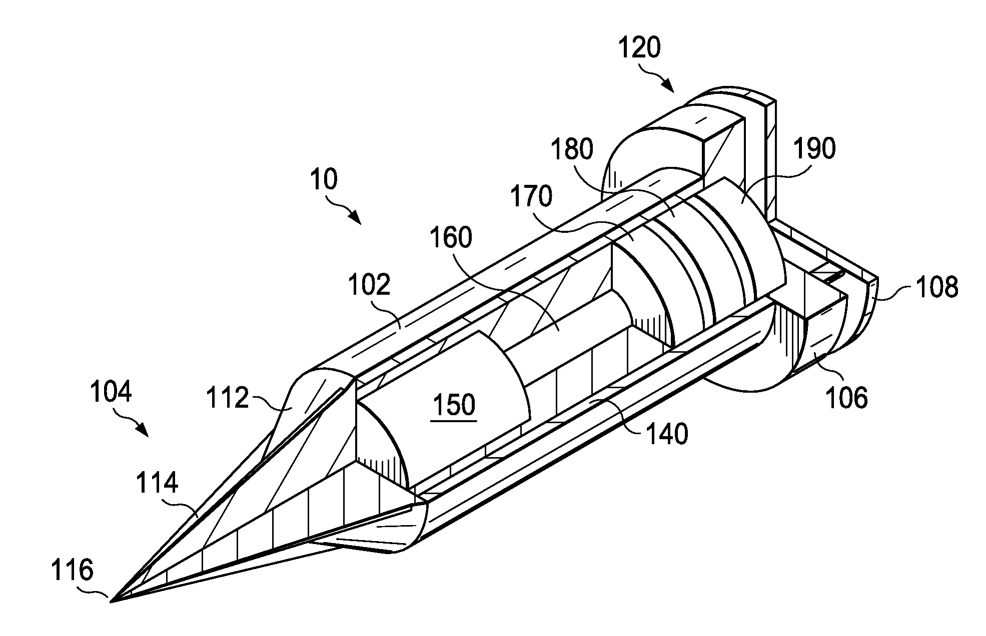
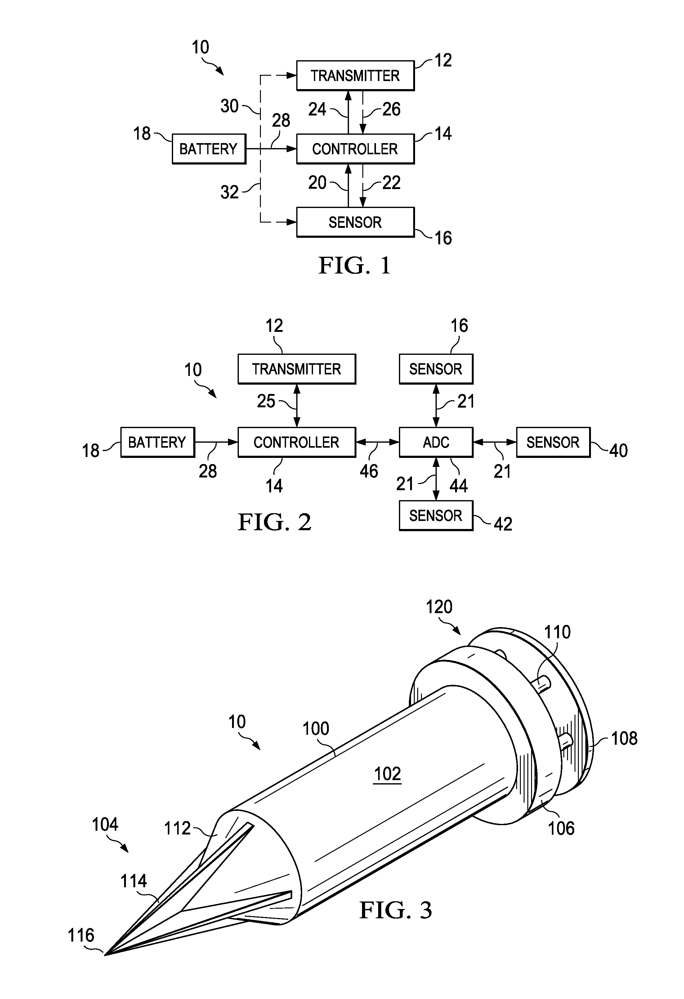
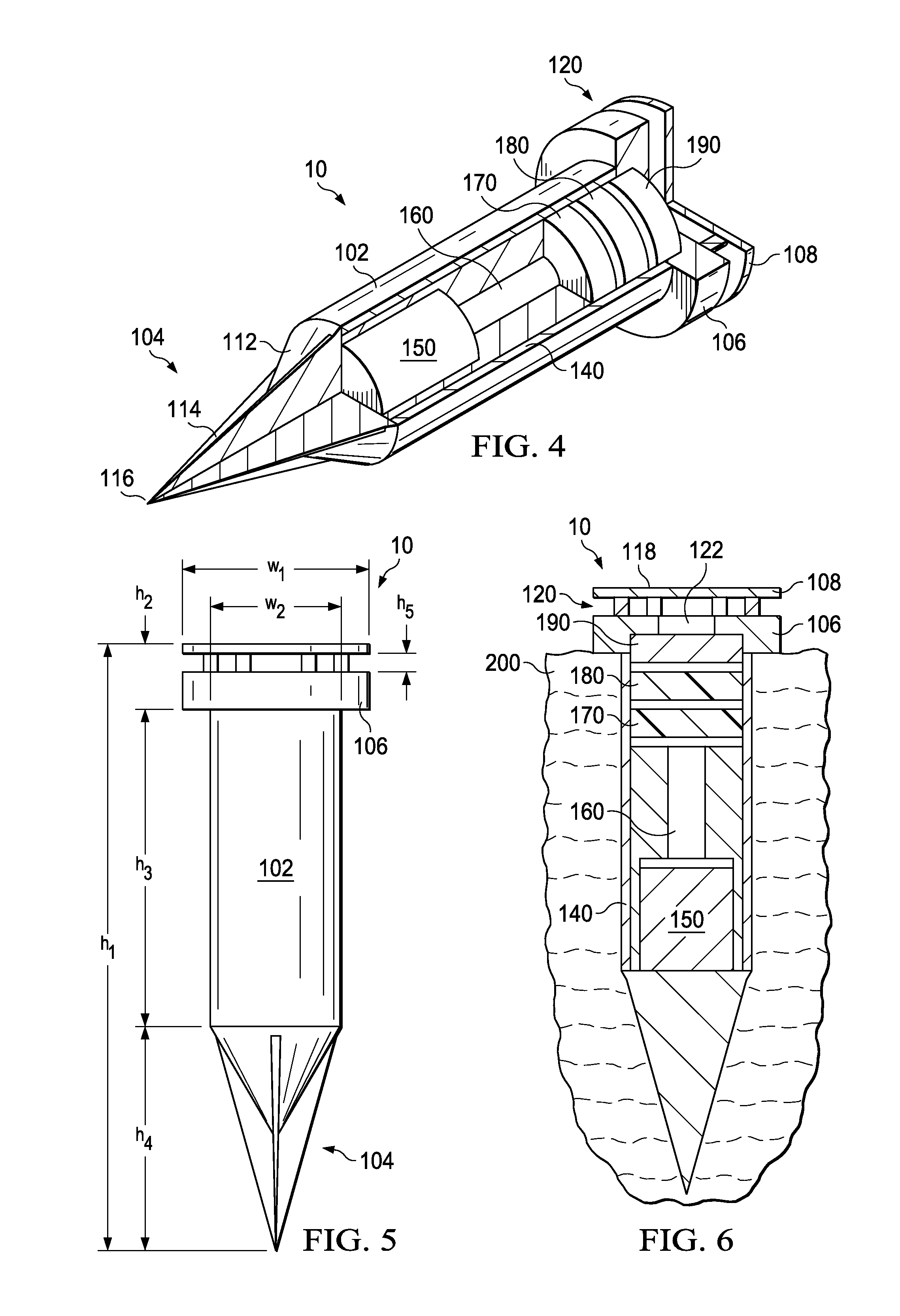
[0016]The outer body of the ground sensor is shaped to make rapid deployment as easy as possible. In particular, the outer body is shaped to aid pushing the ground sensor into the ground. In this respect, the ground sensor is provided with an elongate outer body that is longer than it is wide. The seismic sensor, the controller and the power supply are housed within the elongate outer body. The transmitter may also be housed within the elongate outer body. The seismic sensor, the controller, the power supply, the transmitter (when present within the outer body) and any other components may be stacked one above the other, thus allowing a narrower, longer outer body. Preferably, the transmitter is located at the top of the stack, e.g., at the top of the outer body. Preferably, the seismic sensor is located at the bottom of the stack.
[0018]With this design, the ground sensors may be pushed easily into the ground. To ensure the ground sensor is inserted into the ground to a desired depth, the elongate body may be provided with a collar at an end of ground sensor remote from base. The collar presents a widened portion, preferably with a flat underside. Thus the collar will provide a stop that prevents the ground sensor being pushed too far into the ground. The transmitter may be positioned at the top of the ground sensor adjacent to the collar such that the transmitter is located above ground, provided with a suitable field of view for transmission (e.g., such that the transmission may radiate across the ground rather than be directed mostly upwards).
[0020]Preferably, the ground sensor has a top that is spaced from the collar so as to form an air gap to admit air into interior of elongate outer body. This allows for ventilation and cooling of the components within the ground sensor. The top may be supported above the collar by supports equally spaced around the collar. The height of the ground sensor from the collar upwards, i.e., the portion of the ground sensor exposed above ground when deployed, may have a low profile thereby increasing covertness. For example, this height may be made to be less than 30 mm, preferably less than 20 mm, with a height of 16 mm being particularly preferred.
[0024]This arrangement provides a denser network of ground sensors. This may be illustrative where low cost sensors are being used. For example, each ground sensor may have a sensitivity in the range of 10 to 20 V / m / s, 12 to 18 V / m / s or 14 to 16 V / m / s. The network may comprise more than 25, 50, 100 or 250 ground sensors. This enables a less expensive network to be created with a greater number of low cost ground sensors. As well as reducing overall cost, this arrangement has a further benefit in providing a network with greater resolution due to the greater number of nodes. Moreover, better opportunities are provided in combining data produced from many more ground sensors, as will be described below.
[0028]This arrangement sees responsibility for processing and analyzing the seismic data pushed to the base station, and not imposed upon the ground sensors. This simplifies the requirements for the ground sensors, thus allowing their cost to be reduced. Essentially, data corresponding to the seismic signals is sent from the ground sensors to the base station, where a processor performs the analysis. It is to be understood that the ground sensors may perform some manipulation of the seismic data, for example to reduce noise, to amplify the signal, or to select frequency bands of interest. In any event, the signal transmitted by the ground sensor still corresponds to the seismic signal recorded by the seismic sensor. No analysis has been performed at the ground sensor in the sense that no attempt has been made to determine whether an event corresponding to the movement of a pedestrian or vehicle has occurred.

Problems solved by technology

For example, networks of unattended ground sensors may be used in wooded zones where surveillance using radar systems is not viable.
As a result, each ground sensor is relatively expensive.
In addition, the size of the ground sensors is relatively large and they are designed for long endurance in semi-permanent deployment.
Thus, generally much effort is required to plan the deployment.
The lesser expense of the sensors means that loss of individual sensors, either through damage or by inadvertently being left behind, is tolerable.

Method used


Image

  • Unattended Ground Sensors
  • Unattended Ground Sensors
  • Unattended Ground Sensors

Examples


Embodiment Construction

[0047]An unattended ground sensor 10 is shown schematically in FIG. 1 such that the main components of the ground sensor 10 may be seen clearly. The ground sensor 10 comprises a transmitter 12, a controller 14 and a sensor 16. In this embodiment, sensor 16 is a seismic sensor, such as a geophone. The seismic sensor 16 detects vibrations transmitted to the ground sensor 10 when the ground sensor 10 is deployed in the field. The ground sensor 10 is driven into the ground. Any movement across the ground close to the ground sensor 10 will cause vibrations to travel through the ground. These seismic vibrations impinging on the ground sensor 10 will be detected by the seismic sensor 16, for example the vibrations may be reproduced as a voltage output of the seismic sensor 16. A battery 18 provides power to the ground sensor 10.

[0048]The controller 14 manages operation of the ground sensor 10. The controller 14 receives signals from the seismic sensor 16, as shown by arrow 20. The signals ...


PUM


Abstract

The present disclosure relates to unattended ground sensors for detecting the presence of a pedestrian or vehicle in a monitored area using seismic sensors. Networks of simple and inexpensive sensors are disclosed that may be rapidly deployed. The networks may be formed from a dense array of low cost ground sensors having low sensitivity.

Description

PRIORITY APPLICATION[0001]This application claims the benefit of priority of European Patent Application Serial No. 10382321.7, filed Nov. 29, 2010, entitled “Unattended Ground Sensors”, which is incorporated herein by reference.BACKGROUND INFORMATION[0002]1. Field:[0003]The present disclosure relates to unattended ground sensors for detecting movement of a pedestrian or vehicle in a monitored area using seismic sensors. In particular, the present disclosure relates to a network of simple and inexpensive sensors that may be rapidly deployed, collected and redeployed.[0004]2. Background:[0005]Networks of unattended ground sensors have been developed to make use of wireless sensor networks for surveillance applications. For example, networks of unattended ground sensors may be used in wooded zones where surveillance using radar systems is not viable.[0006]A network typically comprises battery-powered devices that use various sensors to monitor physical or environmental properties, suc...

Claims


Application Information

Patent Timeline
IPC IPC(8): H04B1/06
CPCG01V1/00G01V3/165G01V1/16F41H11/00
Inventor ESTEBAN-CAMPILLO, DAVIDSCARLATTI, DAVIDGARCIA, JAVIER
Owner THE BOEING CO
Learn More