Optical modulation apparatus, method for controlling optical modulator, and control device for optical modulator

a technology of optical modulation and control device, which is applied in the direction of optics, electrical equipment, instruments, etc., can solve the problems of increasing and achieve the effect of reducing the increase of the propagation loss of ligh

Active Publication Date: 2012-05-31
SUMITOMO ELECTRIC IND LTD
View PDF13 Cites 17 Cited by
  • Summary
  • Abstract
  • Description
  • Claims
  • Application Information

AI Technical Summary

Benefits of technology

[0009]It is an object of the present invention to provide an optical modulation apparatus, a method for controlling an optical modulator, and a control device for an optical modulator that can restrain the propagation loss of the light from increasing, and perform the phase adjustment.

Problems solved by technology

However, in this case, there is a problem that a propagation loss of the light increases.

Method used


Image

  • Optical modulation apparatus, method for controlling optical modulator, and control device for optical modulator
  • Optical modulation apparatus, method for controlling optical modulator, and control device for optical modulator
  • Optical modulation apparatus, method for controlling optical modulator, and control device for optical modulator

Examples


first embodiment

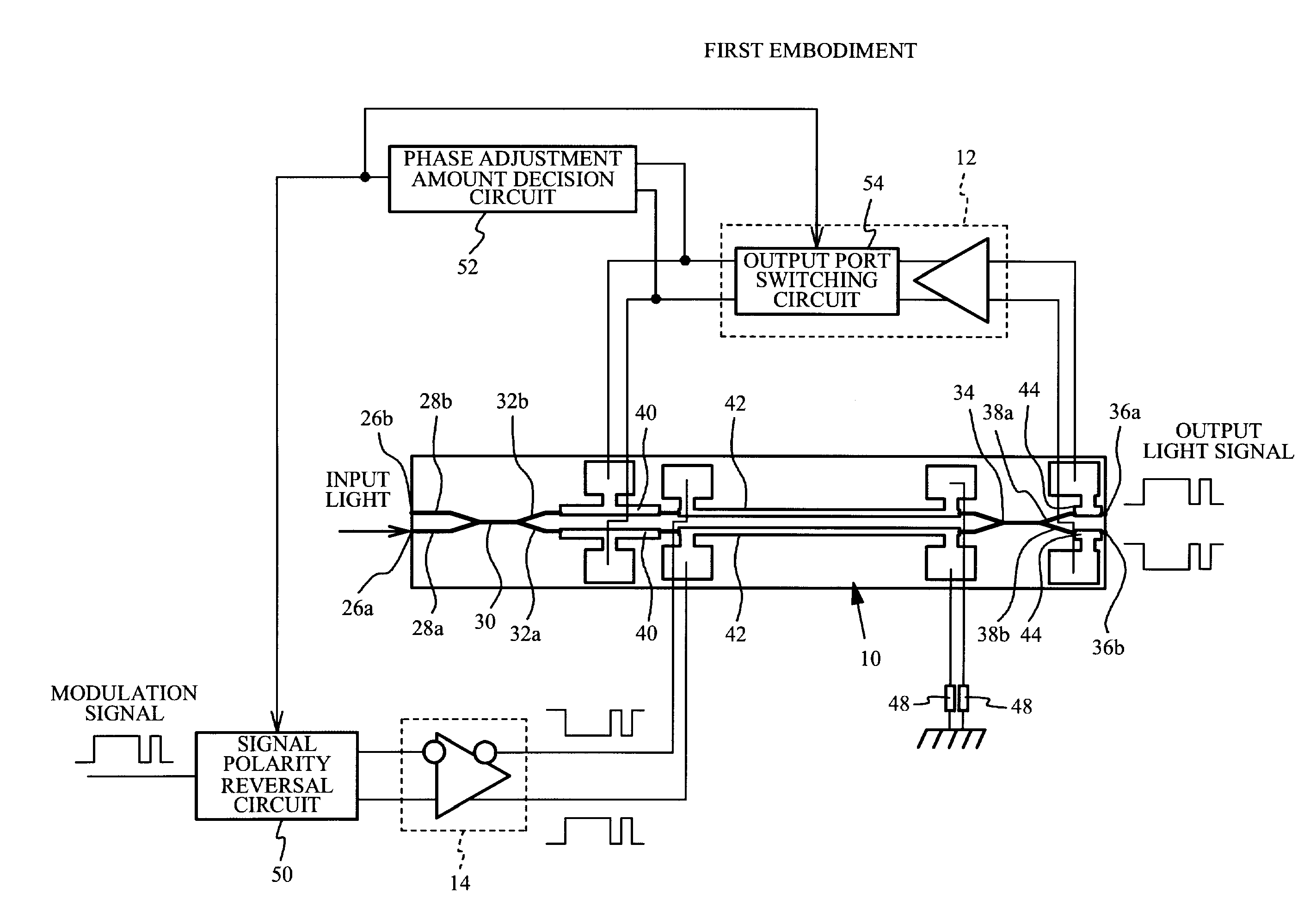
[0041]FIG. 3 is a schematic top view of an optical modulation apparatus according to a first embodiment. As illustrated in FIG. 3, the optical modulation apparatus according to the first embodiment mainly includes the Mach-Zehnder optical modulator 10, the phase adjustment circuit 12 having an output port switching circuit 54, the drive circuit 14, a signal polarity reversal circuit 50, and a phase adjustment amount decision circuit 52. Since the Mach-Zehnder optical modulator 10 of the first embodiment is the same as that of the comparative example 1, a description thereof is omitted.

[0042]The phase adjustment circuit 12 applies the DC voltage that is the phase control signal to the phase adjustment electrode 40 selected by the output port switching circuit 54 to perform the phase adjustment for correcting the shift of the phase difference. Specifically, the phase adjustment circuit 12 applies the DC voltage to the phase adjustment electrode 40 selected by the output port switching...

second embodiment

[0062]The optical modulation apparatus according to the first embodiment may cause a case where the logic of the output light signal used as the modulation light signal is matched with the logic of the modulation signal in a reversal state. Therefore, a second embodiment describes a case where the optical modulation apparatus can make the logic of the output light signal used as the modulation light signal correspond with the logic of the modulation signal.

[0063]FIG. 7 is a schematic top view of the optical modulation apparatus according to the second embodiment. As illustrated in FIG. 7, the optical modulation apparatus according to the second embodiment further includes an optical power decision circuit 56 that decides an optical power detected with each optical power detection electrode 44. The optical power decision circuit 56 decides whether the power of the lights propagated in the first output optical waveguide 38a and the second output optical waveguide 38b are the same as e...

third embodiment

[0076]FIG. 9 is a schematic top view of the optical modulation apparatus according to a third embodiment. As illustrated in FIG. 9, the optical modulation apparatus of the third embodiment differs from that of the first embodiment of FIG. 3 in not including the phase adjustment amount decision circuit 52. The other configurations of the optical modulation apparatus of the third embodiment are the same as those of the optical modulation apparatus of the first embodiment.

[0077]In the optical modulation apparatus according to first embodiment, the phase adjustment for correcting the initial phase difference ΔΦOS caused by the manufacture variation is performed by reducing the amount of the phase adjustment. Here, the initial phase difference ΔΦOS is an unique value of each device. Therefore, the phase adjustment amount decision circuit 52 is temporarily connected to the optical modulation apparatus in advance, and the selected phase adjustment electrode 40 to which the DC voltage is ap...


PUM

PropertyMeasurementUnit
DC voltageaaaaaaaaaa
DC voltage Vp1aaaaaaaaaa
opticalaaaaaaaaaa

Abstract

An optical modulation apparatus including: a Mach-Zehnder optical modulator having two optical waveguides, two output optical waveguides and a join-and-branch portion; a phase adjustment circuit configured to output a phase control signal to phase adjustment electrodes provided respectively on the two optical waveguides; a drive circuit configured to output a modulation signal to modulation electrodes provided respectively on the two optical waveguides as a differential signal, the modulation signal modulating lights propagated in the two optical waveguides; and a signal polarity reversal circuit configured to reverse a polarity of the differential signal to be output from the drive circuit.

Description

CROSS-REFERENCE TO RELATED APPLICATION[0001]This application is based upon and claims the benefit of priority of the prior Japanese Patent Application No. 2010-267622, filed on Nov. 30, 2010, the entire contents of which are incorporated herein by reference.BACKGROUND[0002](i) Technical Field[0003]A certain aspect of the embodiments discussed herein is related to an optical modulation apparatus, a method for controlling an optical modulator, and a control device for an optical modulator.[0004](ii) Related Art[0005]In an optical communication system that superimposes a signal on a light and transmits the light with an optical fiber, an optical modulator that modulates the power of an laser light emitted from a light source, and generates an optical signal is used. For example, a Mach-Zehnder optical modulator is known as the optical modulator (See Japanese Patent Application Publication No. 07-049473).[0006]The Mach-Zehnder optical modulator has a waveguide structure including a bran...

Claims


Application Information

Patent Timeline
Patent Type & Authority Applications(United States)
IPC IPC(8): G02F1/035
CPCG02F1/0123G02F1/2255H04B10/50575H04B10/5057G02F1/2257
Inventor SEKI, MORIHIROUESAKA, KATSUMI
Owner SUMITOMO ELECTRIC IND LTD
Why Eureka
Try Eureka