Screw compressor

Active Publication Date: 2012-05-31
KOBELCO COMPRESSORS CORP
View PDF5 Cites 7 Cited by
  • Summary
  • Abstract
  • Description
  • Claims
  • Application Information

AI Technical Summary

Benefits of technology

[0006]In view of the problems set forth above, the present invention advantageously provides a screw

Problems solved by technology

Therefore, all power used for compressing the gas by an amount corresponding to a difference between the pressures will be wasted.
However, th

Method used


Image

  • Screw compressor
  • Screw compressor
  • Screw compressor

Examples


first embodiment

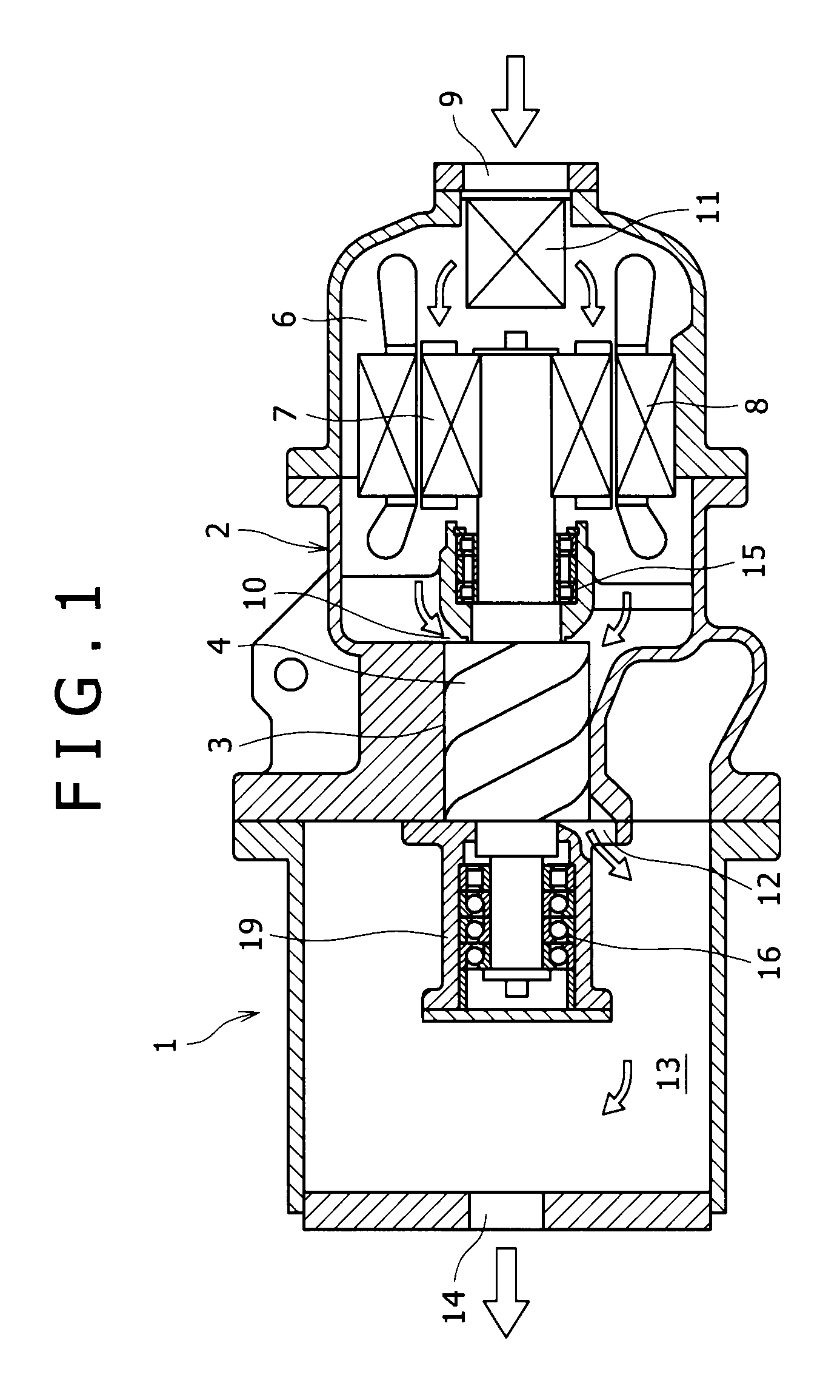
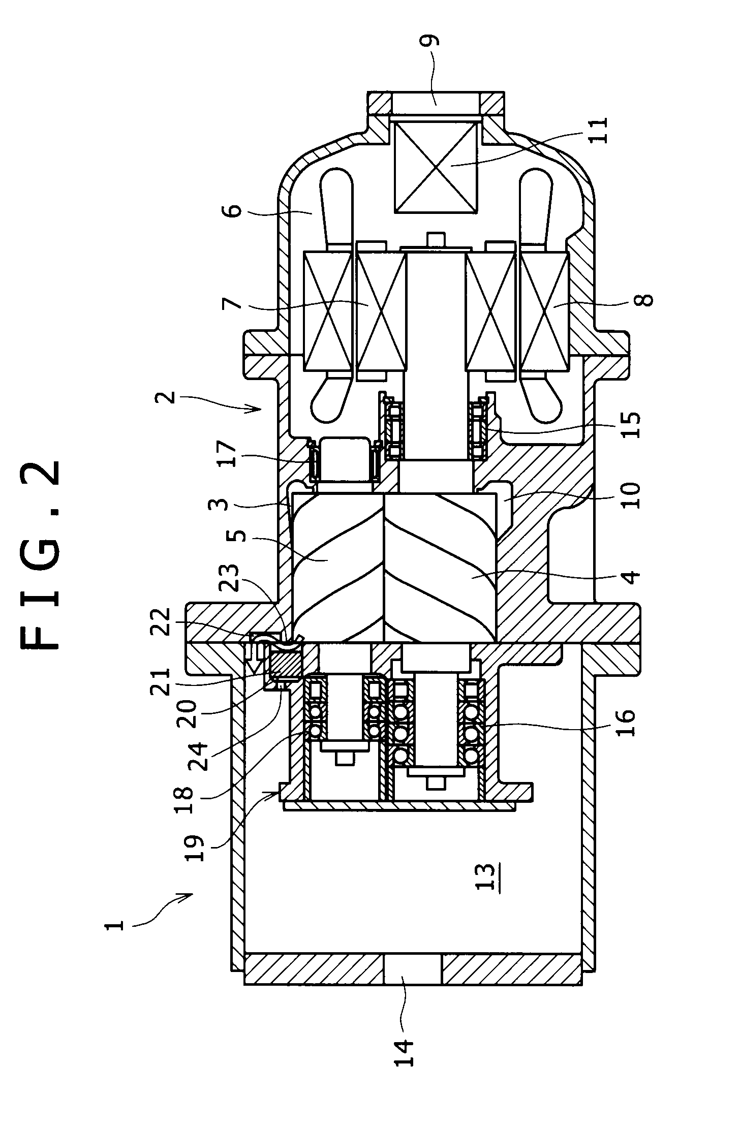
[0018]Hereinafter, preferred embodiments of the present invention will be described with reference to the drawings. FIGS. 1 and 2 show the structure of a screw compressor 1 according to this invention. In the screw compressor 1, a rotor chamber 3 formed in a casing 2 houses a male screw rotor 4 and a female screw rotor 5 which are intermeshing with each other, while a motor chamber 6 also formed in the casing 2 houses a rotor 7 and a stator 8 of a motor for driving the male rotor 4.

[0019]The screw compressor 1 sucks external air from an intake port 9 formed in an end region of the motor chamber 6 and supplies a gas to the rotor chamber 3 via an intake channel 10 which connects the rotor chamber 3 to the motor chamber 6. A supply air filter 11 is installed inside the intake port 9. The gas supplied to the rotor chamber 3 is compressed in a working space defined by the male screw rotor 4 and the female screw rotor 5 in the rotor chamber 3, discharged through a discharge channel 12 int...

second embodiment

[0026]In the second embodiment, because an optimum volume ratio is automatically selected from three volume ratios (of Vi=3.0, 2.5, and 2.0), a power loss resulting from a situation where the screw compressor 1a excessively compresses the gas to a pressure higher than a necessary pressure for demand equipment can be effectively reduced.

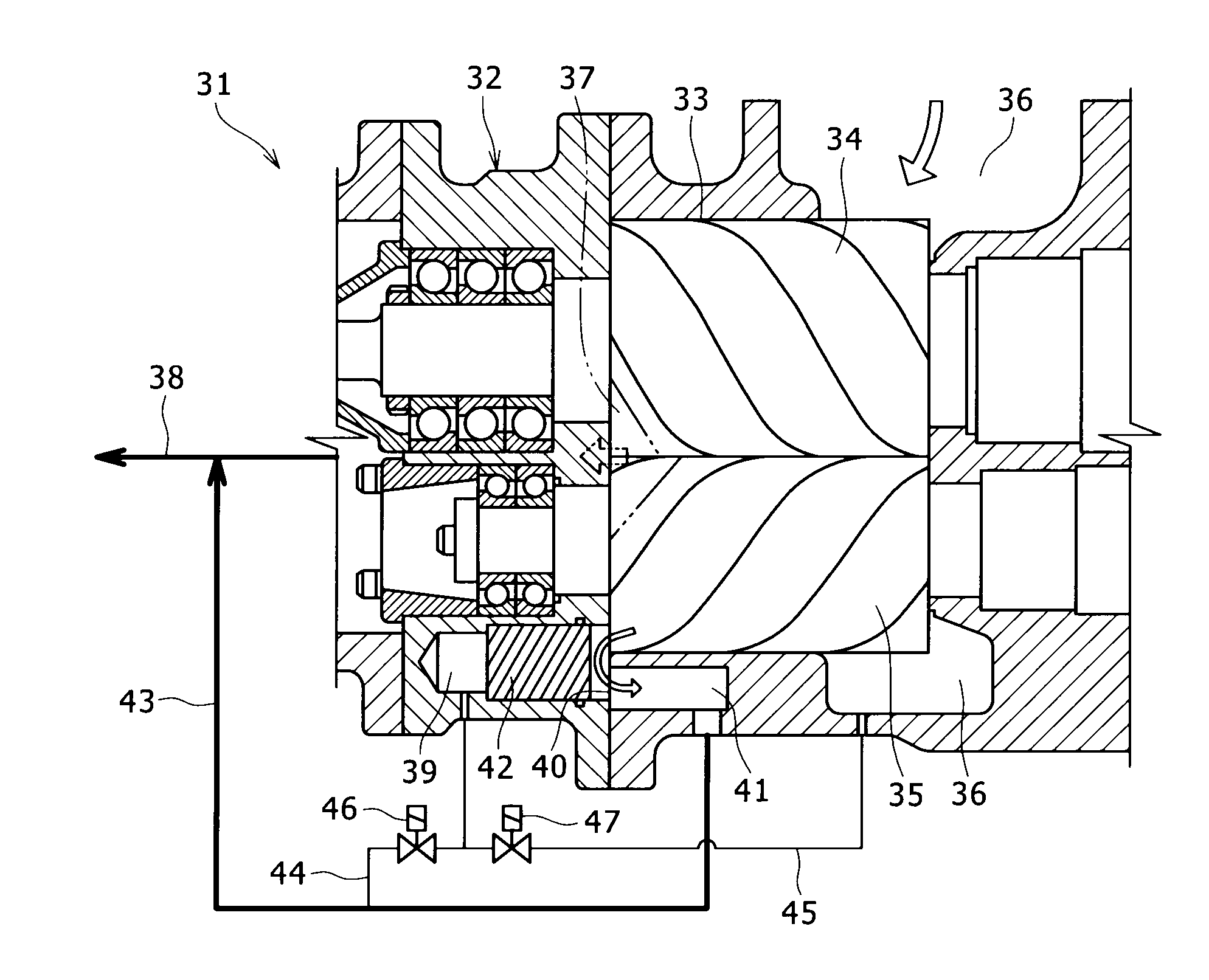
[0027]FIG. 5 shows a screw compressor 31 according to a third embodiment of the present invention. In the screw compressor 31 of the third embodiment, a male screw rotor 34 and a female screw rotor 35 which are intermeshing with each other are housed in a rotor chamber 33 formed in a casing 32, and a gas taken in from an intake channel 36 is discharged into a discharge channel 37. The discharge channel 37 is directly connected to an external discharge pipe arrangement 38.

[0028]Further, in the casing 32, a columnar space 39 opening into an end face of the rotor chamber 33 on the discharge side is formed in such a manner that the columnar space 39 is al...


PUM


Abstract

A screw compressor includes a pair of rotors housed in a rotor chamber. A gas sucked from an intake channel is compressed by the screw rotors and discharged from a discharge channel. A columnar space having a functional end face with an opening into an intermediate pressure section, which is an empty space in the rotor chamber and isolatable from both the intake channel and the discharge channel by the screw rotors. The functional end face has an opening into a bypass channel in communication with the discharge channel. A piston, inserted in the columnar space and brought into contact with the functional end face, separates the intermediate pressure section from the bypass channel when the piston contacts the functional end face. A pressure detection channel allows an area located on an opposite side of the functional end face in the columnar space to communicate with the discharge channel.

Description

BACKGROUND OF THE INVENTION[0001]1. Field of the Invention[0002]This invention relates to a screw compressor.[0003]2. Description of the Related Art[0004]The pressure of an intake channel and the pressure of a discharge channel in a screw compressor are determined by both an air charging unit (an atmospheric pressure in a case of sucking atmospheric air) and demand equipment. On the other hand, the pressure of gas obtained immediately before the gas is discharged from a rotor chamber to the discharge channel in the screw compressor is determined by the pressure of the intake channel and a mechanical compression ratio (a volume ratio) of the screw compressor. When the pressure of gas obtained immediately before the gas is discharged from the rotor chamber is higher than the pressure of the discharge chamber, the gas will be expanded at the moment when the gas is delivered into the discharge chamber, resulting in a drop of the pressure. Therefore, all power used for compressing the ga...

Claims


Application Information

Patent Timeline
IPC IPC(8): F01C1/16
CPCF04C14/26F04C23/008F04C18/16F04C28/16F04C29/12
Inventor TSUBOI, NOBORU
Owner KOBELCO COMPRESSORS CORP
Why Eureka
Try Eureka