Detecting Gas Compounds For Downhole Fluid Analysis

a technology of gaseous compounds and fluid analysis, which is applied in the field of in situ detection of gaseous compounds in a, can solve the problems of insufficient sulfide content estimation, and inability to accurately estimate sulfide conten

Active Publication Date: 2012-06-07
SCHLUMBERGER TECH CORP
View PDF30 Cites 32 Cited by
  • Summary
  • Abstract
  • Description
  • Claims
  • Application Information

AI Technical Summary

Benefits of technology

[0006]In accordance with an embodiment of the invention, apparatus for performing in situ analysis of borehole fluid includes a gas separation system and a gas detection system. The gas separation system may include a membrane. The gas separated from the fluid by the membrane may be detected by techniques such as reaction with another material or spectroscopy. When spectroscopy is employed, a test chamber is used to hold the gas undergoing test. Various techniques may be employed to protect the gas separation system from damage due to pressure differential. For example, a separation membrane may be integrated with layers that provide strength and rigidity. The integrated separation membrane may include one or more of a water impermeable layer, gas selective layer, inorganic base layer and metal support layer. The gas selective layer itself can also function as a water impermeable layer. The metal support layer enhances resistance to differential pressure. Alternatively, the test chamber may be filled with a liquid or solid material.
[0008]One of the advantages of the invention is that borehole fluid can be analyzed in situ. In particular, gas is separated from the fluid and detected within the borehole. Consequently, time consuming fluid retrieval and errors caused by changes to fluid samples due to changes in conditions between the borehole and the environment are at least mitigated.

Problems solved by technology

For example, CO2 corrosion and H2S stress cracking are leading causes of mechanical failure of production equipment.
However, retreiving samples for laboratory analysis are time consuming.
For example, because hydrogen sulfide gas readily forms non-volatile and insoluble metal sulfides by reaction with many metals and metal oxides, analysis of a fluid sample retreived with a metallic container can result in an inaccurate estimate of sulfide content.
This presents a technological problem because known fluid analysis techniques that can be used at the surface are impractical in the borehole environment due to size limitations, extreme temperature, extreme pressure, presence of water, and other factors.
Another technological problem is isolation of gases, and particular species of gas, from the borehole fluid.

Method used


Image

  • Detecting Gas Compounds For Downhole Fluid Analysis
  • Detecting Gas Compounds For Downhole Fluid Analysis
  • Detecting Gas Compounds For Downhole Fluid Analysis

Examples


Embodiment Construction

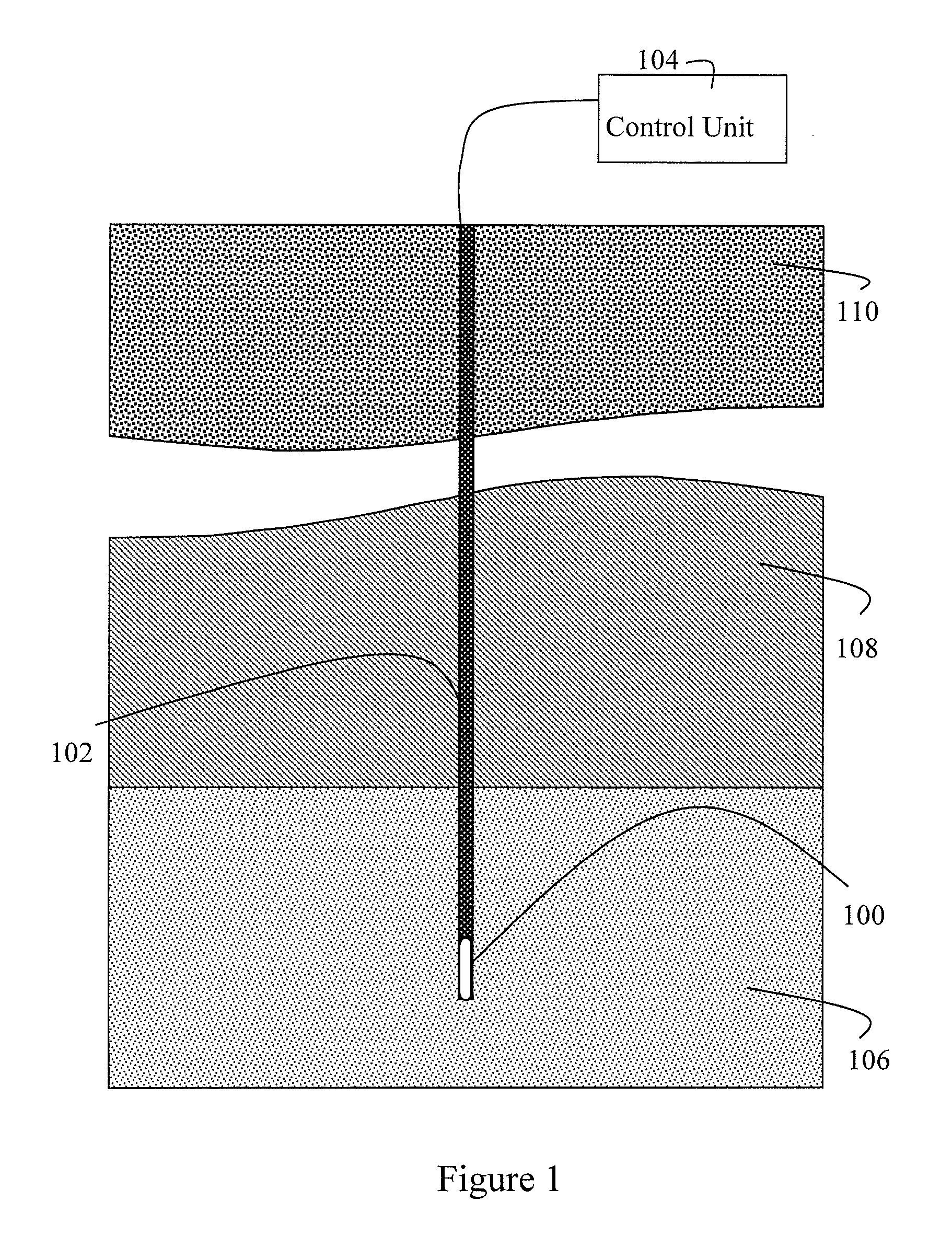
[0019]Referring to FIG. 1, a wireline logging tool (106) is suspended from an armored cable (108), and may have optional centralizers (not shown). The cable (108) extends from the borehole (104) over a sheave wheel (110) on a derrick (112) to a winch forming part of surface equipment, which may include an analyzer unit (114). Well known depth gauging equipment (not shown) may be provided to measure cable displacement over the sheave wheel (110). The tool (106) may include any of many well known devices to produce a signal indicating tool orientation. Processing and interface circuitry within the tool (106) amplifies samples and digitizes the tool's information signals for transmission and communicates them to the analyzer unit (114) via the cable (108). Electrical power and control signals for coordinating operation of the tool (106) may be generated by the analyzer unit (114) or some other device, and communicated via the cable (108) to circuitry provided within the tool (106). The...


PUM


Abstract

A gas separation and detection tool for performing in situ analysis of borehole fluid is described. The tool comprises a sampling chamber for a downhole fluid. The sample chamber comprises a detector cell with an opening. The tool also comprises a gas separation module for taking a gas from the downhole fluid. The gas separation module comprises a membrane located in the opening, a support for holding the membrane, and a sealant applied between the housing and the membrane or support. Moreover, the tool comprises a gas detector for sensing the gas.

Description

CROSS REFERENCE TO RELATED APPLICATION[0001]This application is a continuation-in-part of U.S. patent application Ser. No. 12 / 198,129 filed Aug. 26, 2008 and entitled “DETECTING GAS COMPOUNDS FOR DOWNHOLE FLUID ANALYSIS,” which is hereby incorporated in its entirety by this reference.FIELD OF THE INVENTION[0002]The invention is generally related to downhole fluid analysis, and more particularly to in situ detection of gaseous compounds in a borehole fluid.BACKGROUND OF THE INVENTION[0003]Phase behavior and chemical composition of borehole fluids are used to help estimate the viability of some hydrocarbon reservoirs. For example, the concentration of gaseous components such as carbon dioxide, hydrogen sulfide and methane in borehole fluids are indicators of the economic viability of a hydrocarbon reservoir. The concentrations of various different gasses may be of interest for different reasons. For example, CO2 corrosion and H2S stress cracking are leading causes of mechanical failur...

Claims


Application Information

Patent Timeline
Patent Type & Authority Applications(United States)
IPC IPC(8): E21B49/00
CPCE21B49/005G01N33/2823E21B49/08
Inventor LAWRENCE, JIMMYJONES, TIM G. J.INDO, KENTAROYAMATE, TSUTOMUMATSUMOTO, NORIYUKITORIBIO, MICHAEL M.YOSHIUCHI, HIDETOSHIMEREDITH, ANDREWLAWRENCE, NATHAN S.JIANG, LIFUJISAWA, GOMULLINS, OLIVER C.
Owner SCHLUMBERGER TECH CORP
Why Eureka
Try Eureka