Output Stage of a Power Amplifier Having a Switched-Bulk Biasing and Adaptive Biasing

a power amplifier and output stage technology, applied in the direction of amplifiers, amplifiers with semiconductor devices only, amplifiers with semiconductor devices, etc., can solve the problems of 2-4v, 2-4v, and a much lower device breakdown voltage (bv) to achieve and require more complex architectures to handle the required high output power

Active Publication Date: 2012-06-07
QORVO INT PTE LTD
View PDF3 Cites 49 Cited by
  • Summary
  • Abstract
  • Description
  • Claims
  • Application Information

AI Technical Summary

Benefits of technology

[0030]FIG. 11 is a schematic diagram of a an overvoltage protection of th...

Problems solved by technology

The high cost of the exotic bipolar HBT process increases the overall cost of the system.
However, the main drawback of the CMOS PA solutions is the much lower device breakdown voltage (BV), e.g., 2-4V, that requires more complex architectures to handle the required high output power.
The main drawback of this solution is the need for a large...

Method used


Image

  • Output Stage of a Power Amplifier Having a Switched-Bulk Biasing and Adaptive Biasing
  • Output Stage of a Power Amplifier Having a Switched-Bulk Biasing and Adaptive Biasing
  • Output Stage of a Power Amplifier Having a Switched-Bulk Biasing and Adaptive Biasing

Examples


Embodiment Construction

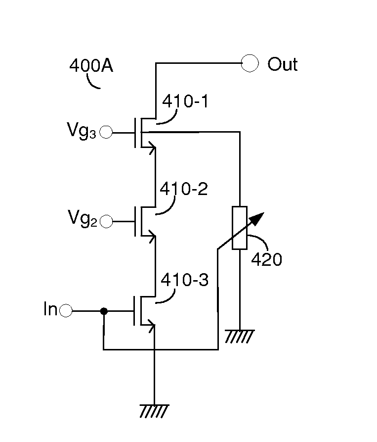
[0031]A power amplifier (PA) using switched-bulk biasing to minimize the risk of output stage snapback effect is shown. An adaptive biasing of the output stage prevents device breakdown while accommodating large voltage swings. These protection techniques can be applied to all types of cascode configurations of a PA, including, single-ended, differential, quadrature, segmented and any combination thereto.

[0032]Reference is made to FIG. 2A that depicts schematic diagram 200A of a cascode configuration of a PA output stage. To withstand the high output voltage of a high power PA the output stage is divided into several stacked devices in a cascode configuration having the voltages V1, Vk and Vn for devices 230, 220 and 210 respectively. Since the last device 210 in the stack sees the full output voltage at least at one terminal, if not across two terminals, it is usually implemented with a high voltage thick gate field-effect transistor (FET). FIG. 2B provides therefore a preferred em...


PUM


Abstract

A power amplifier (PA) using switched-bulk biasing to minimize the risk of output stage snapback effect is disclosed. An adaptive biasing of the output stage prevents device breakdown while accommodating large voltage swings. These protection techniques can be applied to all types of cascode configurations of a PA, including single-ended, differential, quadrature, segmented and any combination thereto.

Description

CROSS-REFERENCE TO RELATED APPLICATIONS[0001]This application claims the benefit of U.S. Provisional Patent Application No. 61 / 419,857 filed Dec. 5, 2010.BACKGROUND OF THE INVENTION[0002]1. Field of the Invention[0003]The invention generally relates to power amplifiers (PAs) having cascode amplifier stages, and more specifically to PAs for high transmitted power communications when the devices need to withstand very large peak signal values.[0004]2. Prior Art[0005]Many of the modern wireless communication standards require very large power levels to be delivered by the power amplifier (PA) to an antenna. Some examples are cellular telephony with power up to +35 dBm at the PA output, wireless local area networks (WLAN), WiMax, etc. This results in very large peak voltages of the output of the active PA, which outputs may reach values of 10-15V.[0006]Historically high power PAs have been dominated by bipolar implementations, e.g., SiGe heterojunction bipolar transistor (HBT), GaAs HBT...

Claims


Application Information

Patent Timeline
IPC IPC(8): H03F3/16H03F1/22
CPCH03F1/0272H03F1/223H03F1/301H03F1/523H03F3/19H03F3/211H03F2203/45394H03F2200/108H03F2200/18H03F2200/405H03F2200/426H03F2200/447H03F2200/541H03F3/245
Inventor SCOTT, BAKERMAXIM, GEORGEFRANCK, STEPHEN
Owner QORVO INT PTE LTD
Why Eureka
Try Eureka