Optical Communication System, Device and Method Employing Advanced Coding and High Modulation Order

a communication system and high modulation order technology, applied in the field of optical communication systems, can solve the problems of reducing reach, adversely affecting spectrum efficiency and system cost, and affecting system cost, and achieve the effect of improving system sensitivity and high speed

Active Publication Date: 2012-06-07
WUHAN POST & TELECOMM RES INST CO LTD
View PDF9 Cites 65 Cited by
  • Summary
  • Abstract
  • Description
  • Claims
  • Application Information

AI Technical Summary

Benefits of technology

[0008]The present invention provides a transmitting device, a receiving device, an optical communication system, and methods, which improve the system sensitivity and achieve a high speed (e.g., over 1-Tb / s) transmission per single channel over a long-haul distance (e.g. over 1000-km).

Problems solved by technology

One of the main limitations is enhanced nonlinearity due to continuous ultra-broad spectrum of a Tb / s signal which results in reach reduction compared to current 100-Gb / s transport.
However, a common way to use such kinds of codes introduces some overhead.
The increased overhead (lower rate) codes further improve the system performance, but also require higher bandwidth that adversely affect the spectrum efficiency and the system cost.
However, such kind of code has its limitation that it is very sensitive to phase issue on the constellation, which means the improvement may degrade during the long-haul transmission.
Although such scheme can be used to improve the system performance, it is not a good choice for long-haul transmission due to its ultra sensitivity to phase noises.
To achieve good improvement, the computation complexity of TCM becomes very heavy.
However, to realize more than 1-Tb / s transmission using such modulation format for over 1000-km SSMF reaches, the conventional technique for QPSK modulation appears to be insufficient.

Method used


Image

  • Optical Communication System, Device and Method Employing Advanced Coding and High Modulation Order
  • Optical Communication System, Device and Method Employing Advanced Coding and High Modulation Order
  • Optical Communication System, Device and Method Employing Advanced Coding and High Modulation Order

Examples


first embodiment

[0032]An optical communication system, a transmitting device, and a receiving device according to the invention are described in detail with reference to FIGS. 1-3.

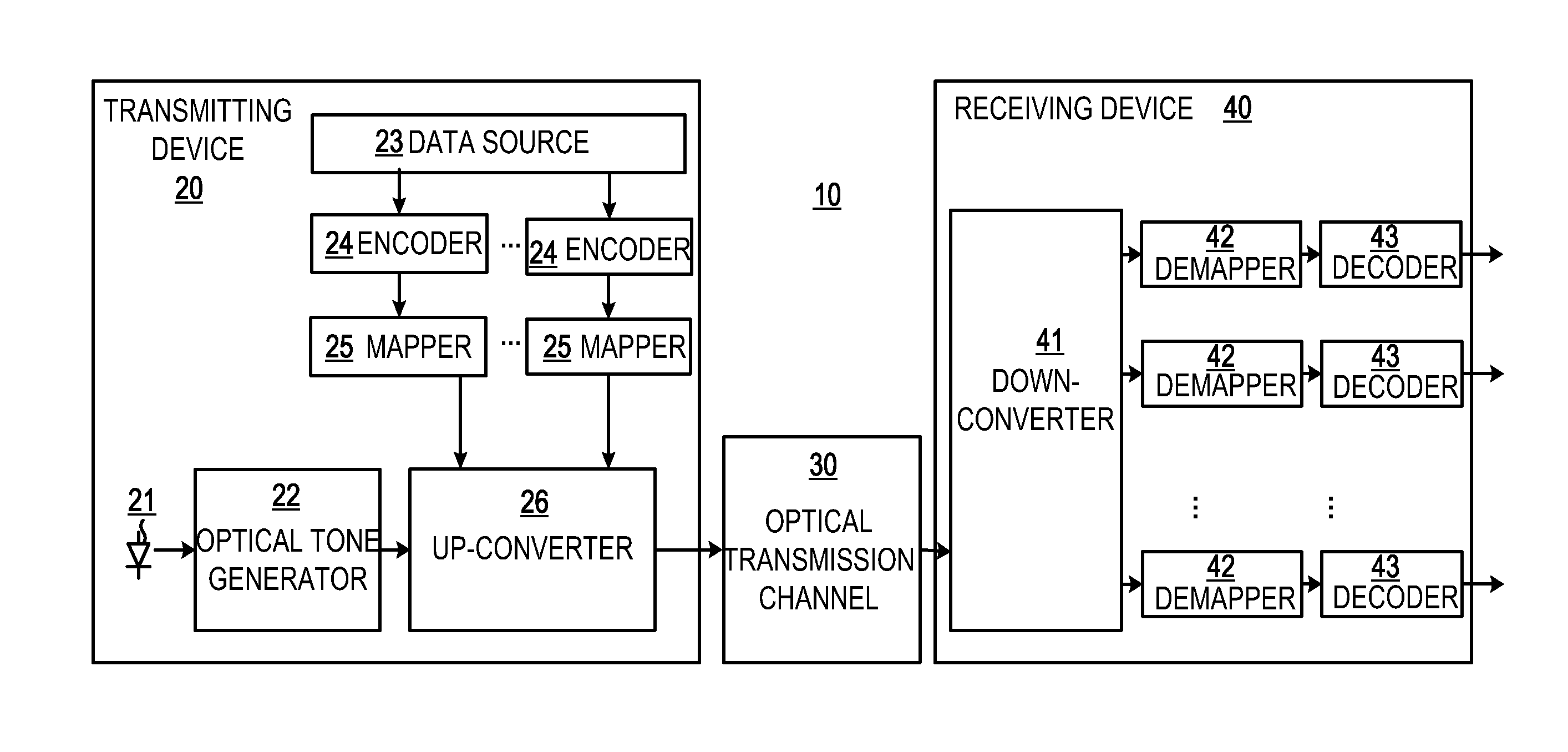
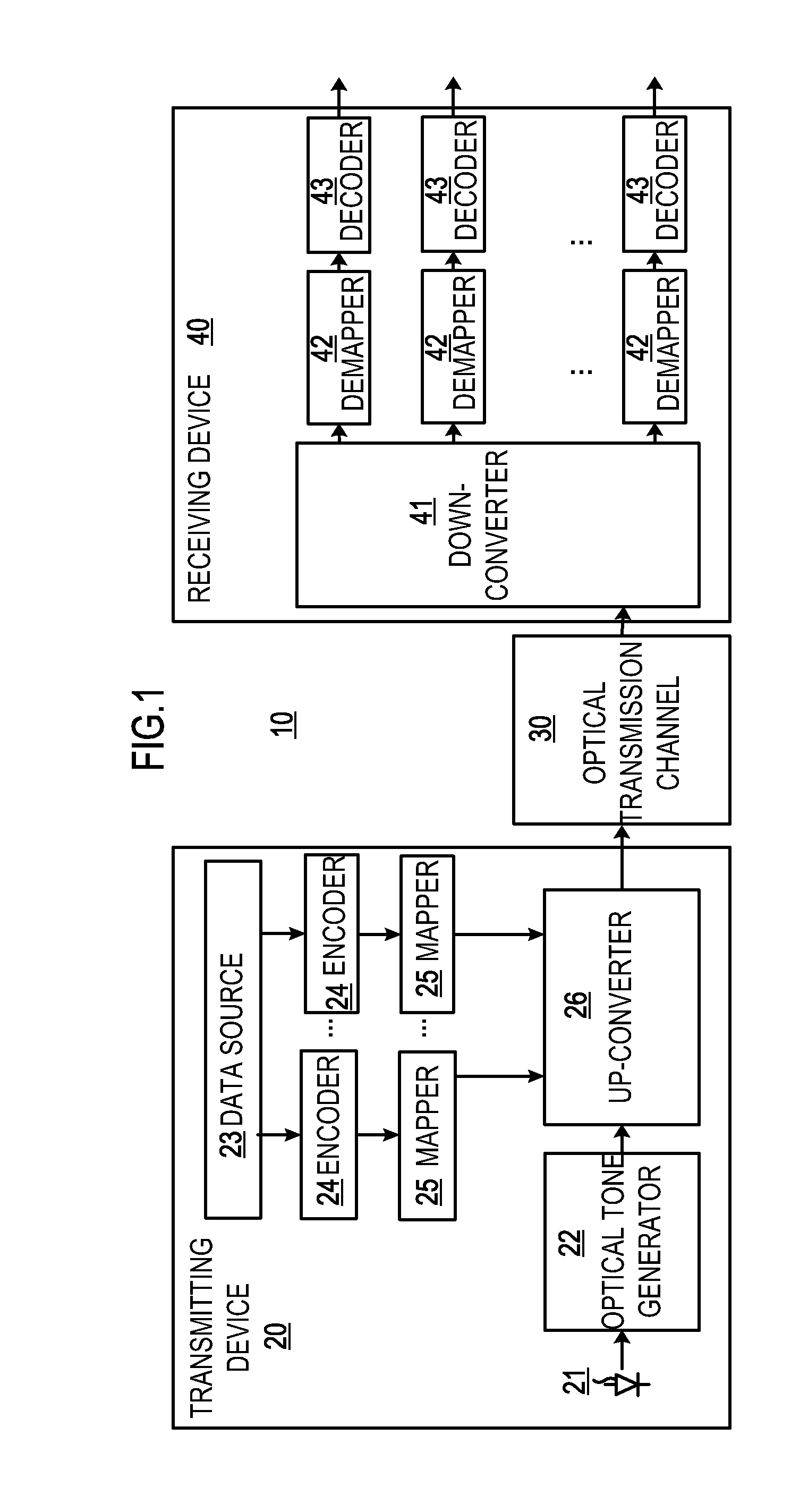
[0033]Referring now to FIG. 1, there is shown a system configuration of a high speed (e.g. over 1-Tb / s) long-haul (e.g., over 1000-km) optical transmission system 10 according to a first embodiment of the present invention. The optical communication system 10 includes a transmitter (also referred to as a transmission device, or a transmitting device) 20, an optical transmission channel 30, and a receiver (also referred to as a receiving device) 40. The transmitter 20 is coupled to the optical transmission channel 30. The optical transmission channel 30 in turn is coupled to the receiver 40.

[0034]The transmitter 20 transmits an optical signal containing data to the receiver 40 via the optical transmission channel 30. The transmitter 20 includes an optical source 21, an optical tone generator 22, a data source 23, one or mo...

second embodiment

[0071]FIG. 9 shows a schematic configuration of a high speed (e.g. over 1-Tb / s) long-haul (e.g. over 1000-km) optical communication system according to the present invention.

[0072]As shown in FIG. 9, the optical communication system 70 comprises a transmitter (also referred to as a transmission device or a transmitting device) 80, the optical transmission channel 30, and a receiver (also referred to as a receiving device) 90. The transmitter 80 according to the second embodiment of the invention is described.

[0073]The transmitter 80 transmits an optical signal containing data to the receiver 90, and comprises an optical source 81, an optical tone generator 82, and an optical signal generator 83.

[0074]The optical source 81, which may be a single laser source, generates a CW optical carrier at a predetermined wavelength, and the optical tone generator 82 generates Nt optical tones from the single optical source. The optical signal generator 83 generates the optical signal, and then tr...


PUM


Abstract

A transmitting device, a receiving device, an optical communication system, and associated methods are provided. The transmitting device transmits an optical signal containing data, and comprises: an optical tone generator for generating at least one optical tone; at least one encoder for performing advanced coding on at least one data signal respectively, each of the at least one data signal carrying a part of the data; at least one mapper for performing high order modulation on the at least one coded data signal; and an up-converter for up-converting the at least one high-order-modulated data signal into the optical signal to be outputted through the at least optical tone. Thereby, high speed (e.g., over 1-Tb/s) transmission per single channel over a long-haul distance (e.g. over 1000-km) with error-free recovery may be achieved.

Description

CROSS REFERENCE TO RELATED APPLICATIONS[0001]This application relates to a concurrently filed, co-pending, and commonly assigned U.S. patent application Ser. No. ______, entitled “System and Method for Subcarrier Recovery at Local Oscillator Frequency in Optical OFDM System” by Qi Yang et al., the disclosure of which is hereby incorporated by reference herein in its entirety.FIELD OF THE INVENTION[0002]The present invention relates generally to optical communication systems, and more particularly to transmitters and receivers that operate at a high-speed transmission per single channel over a long-haul distance.DESCRIPTION OF RELATED ART[0003]Research on optical transmission has generally been concentrated on the following four aspects: increase a data rate, increase a transmission reach, increase spectrum efficiency, and improve receiver sensitivity. With fast growing of optical networks, necessity and importance for the above-mentioned four aspects becomes much obvious.[0004]Resea...

Claims


Application Information

Patent Timeline
Patent Type & Authority Applications(United States)
IPC IPC(8): H04B10/00H04B10/06H04B10/04
CPCH04B10/516H04J14/02H04L1/0065H04J14/0298H04J14/06H04J14/0279
Inventor YANG, QILIU, WUHE, ZHIXUESHIEH, WILLIAMDJORDJEVIC, IVAN B.YANG, ZHUYU, SHAOHUA
Owner WUHAN POST & TELECOMM RES INST CO LTD
Why Eureka
Try Eureka