
Wind farm island operation

a technology for wind farms and islands, applied in the direction of motors, engine control, emergency control, etc., can solve the problems of maintenance and refueling, the typical use of uninterruptible conventional wind farms, and the challenges of technology, and achieve the effect of efficient and cheap

Active Publication Date: 2012-06-14
XEMC DARWIND
View PDF6 Cites 51 Cited by
  • Summary
  • Abstract
  • Description
  • Claims
  • Application Information

AI Technical Summary

Benefits of technology

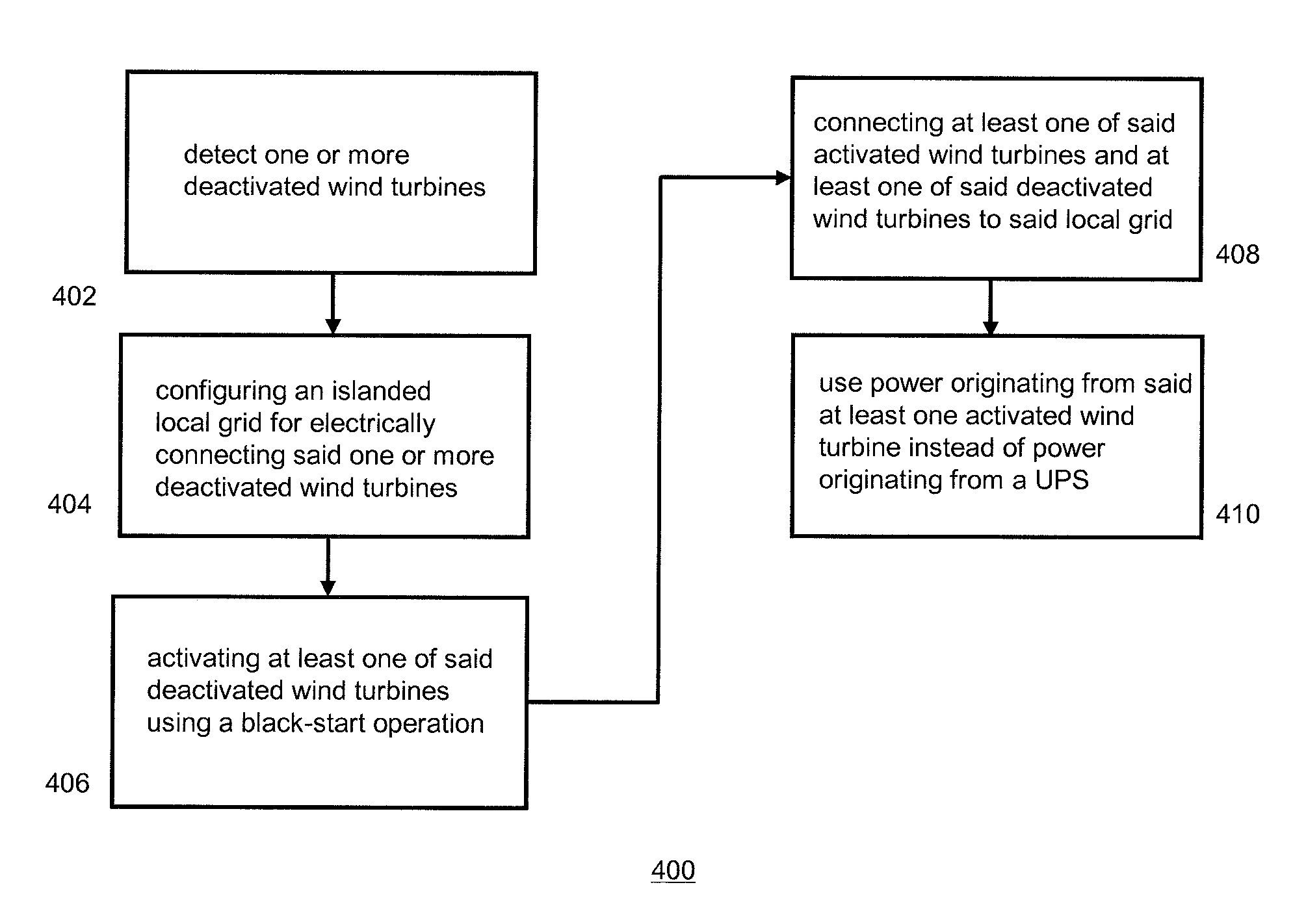
[0010]The operational wind turbine thus acts as an auxiliary power supply, which may either be a supplemental auxiliary power supply to the auxiliary power supply of each wind turbine or a main auxiliary power supply replacing the auxiliary power supply of each of the wind turbines. The method thus provides an efficient and cheap way of supplying power to an islanded group of wind turbines. The method is especially effective when deactivation of large groups of wind turbines over a longer period is necessary, for example during grid maintenance or defects. Moreover, the method reduces the necessity of using combustion type generator sets.

Problems solved by technology

The installation and operations of such wind parks provide some technological challenges.
One of the problems faced in wind farm operations relates to so-called islanding.
A conventional wind farm turbine typically uses an uninterruptible power supply (comprising e.g. a battery system, super capacitors and / or a diesel generator set) as the auxiliary power source.
Diesel generators however require maintenance and refueling and are thus less suitable for use in offshore and / or remote wind farm systems.
Moreover, batteries are sensitive to temperature changes and—in order to ensure a power supply over a long duration—typically a large number of batteries is required.

Method used


Image

  • Wind farm island operation
  • Wind farm island operation
  • Wind farm island operation

Examples


Embodiment Construction

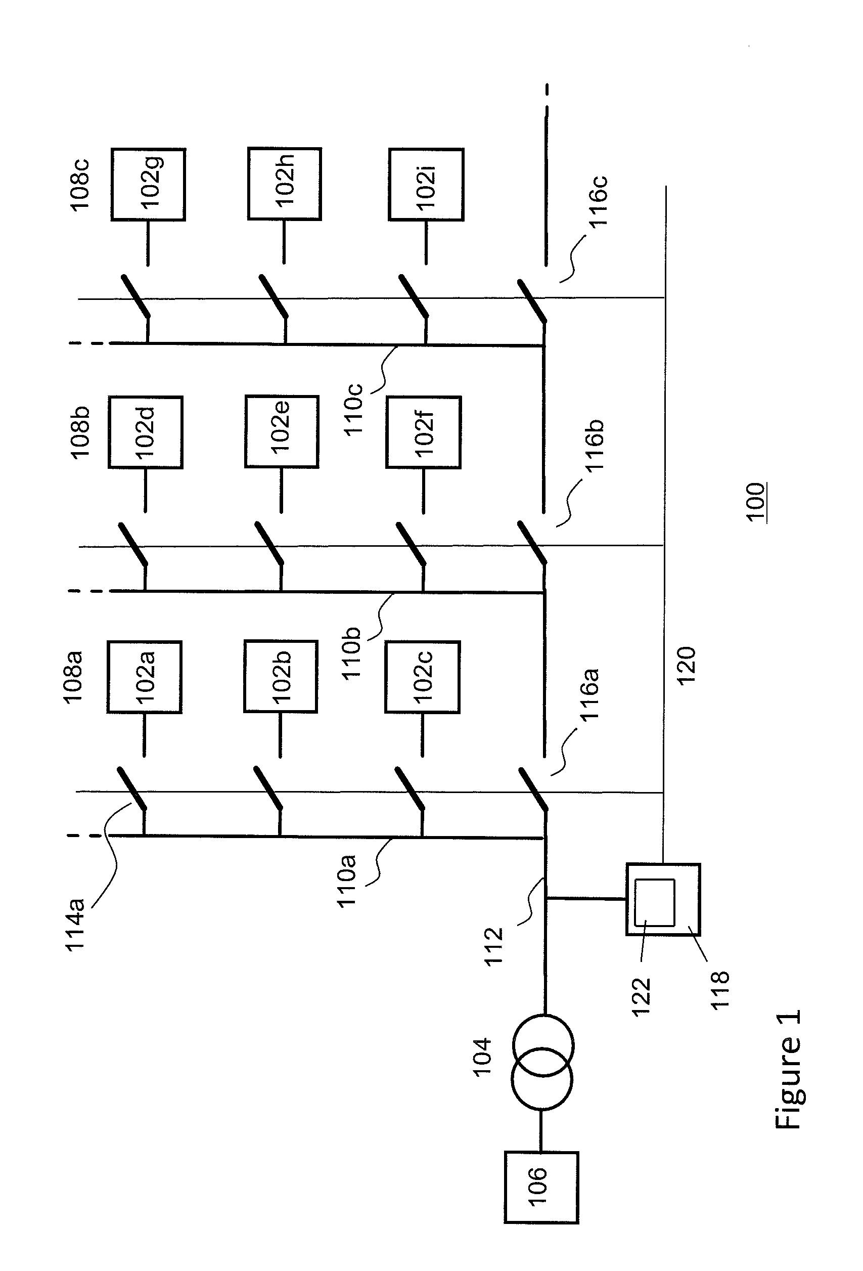
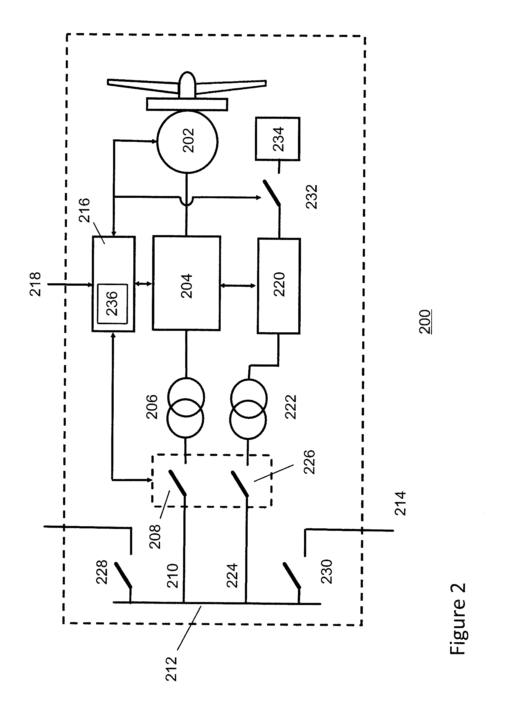
[0025]FIG. 1 depicts a schematic of an exemplary wind farm system 100 according to one embodiment of the invention. The wind farm comprises a plurality of wind turbines 102a-102i connected via one or more switches, e.g. circuit breakers, and one or more (substation) transformers 104 to an external power transmission system (i.e. the main power grid, typically the public power grid) 106, e.g. a three phase 50 or 60 Hz power grid, or a high voltage direct current (HVDC) link. The wind turbines of the wind farm may be electrically interconnected using a local power transmission system (i.e. the local grid) which may comprise power transmission lines 110a-110c and one or more main power transmission lines 112 for connecting the wind farm system to the external power transmission system. In the embodiment of FIG. 1 the wind turbines may be arranged in linear arrays 108a-108c (“strings”), however other interconnecting arrangement well known in the art are also possible. For example in a f...


PUM


Abstract

A method and a system are described for island operation of at least two wind turbines associated with a wind farm, wherein said wind farm is configured for providing power generated by wind turbines in said wind farm to a main grid and wherein the method comprises: detecting at least two or more deactivated wind turbines in said wind farm, said deactivated wind turbines being disconnected from said main grid; configuring at least one islanded local grid for electrically connecting said two or more deactivated wind turbines; activating at least one of said deactivated wind turbine using a black start operation; and, connecting said at least one activated wind turbine and at least one of said deactivated wind turbines to said local grid, said activated wind turbine acting as a power supply for said at least one deactivated wind turbine connected to said local grid.

Description

CROSS-REFERENCE TO RELATED APPLICATION[0001]This application is a Section 371 National Stage Application of International Application PCT / EP2010 / 054524 filed Apr. 6, 2010 and published as WO / 2010 / 112616 in English.FIELD OF THE INVENTION[0002]Aspects of the invention relate to wind farm island operation and, in particular, though not exclusively, to a method and a controller for island operation of at least two wind turbines associated with a wind farm, said wind farm being configured for providing power generated by wind turbines in said wind farm to a main grid, a wind turbine and a wind farm system using such controller and a computer program product for executing such method.BACKGROUND OF THE INVENTION[0003]The discussion below is merely provided for general background information and is not intended to be used as an aid in determining the scope of the claimed subject matter.[0004]Wind turbine technology and in particular offshore wind turbine technology is a rapidly developing f...

Claims


Application Information

Patent Timeline
IPC IPC(8): H02J3/00
CPCF03D9/005F05B2240/96F05B2270/107Y02E10/76H02J2003/388H02M7/49Y02E10/72F05B2270/1074F03D9/257H02J3/388F03D7/0284
Inventor BODEWES, FLORENTIUS JOANNESSTRIK, FRANCISCUS LEONARDUS HENDRICUS
Owner XEMC DARWIND
Learn More